 Laird Connectivity is now Ezurio
BL654 Series Bluetooth Module with NFC


Overview
Now available: BL654PA Series with Integrated Power Amplifier (Skyworks part # SKY66112-11)
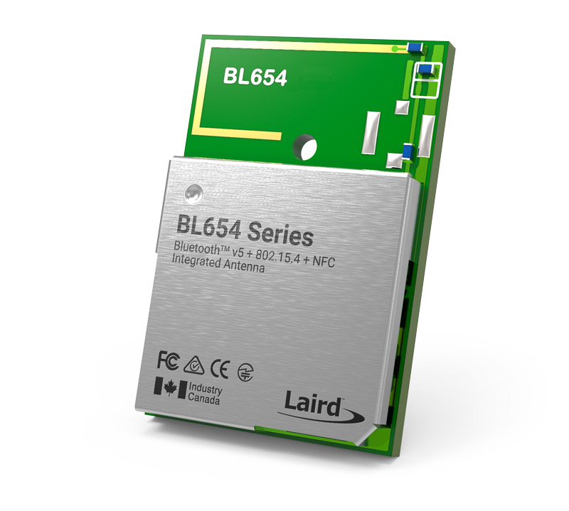
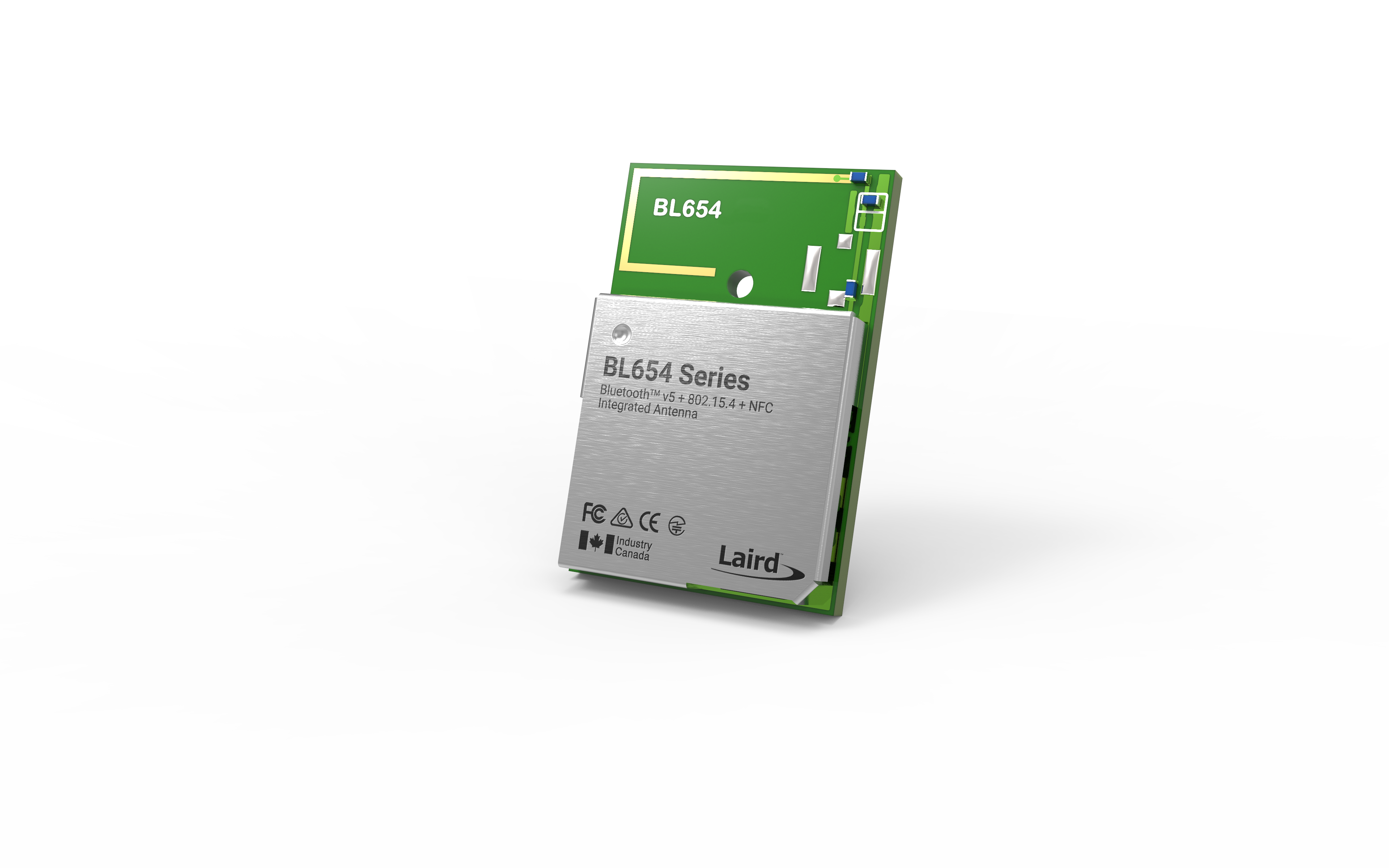
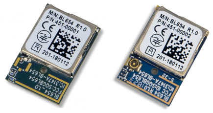
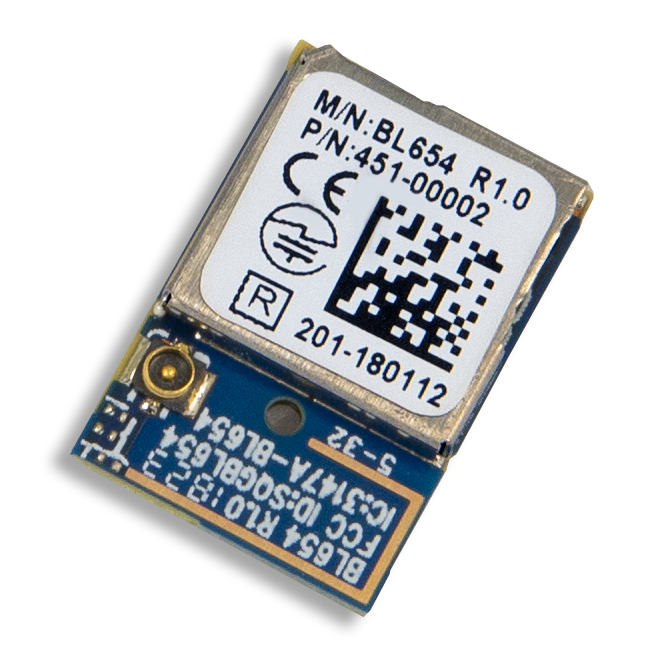
Building on Ezurio's (formerly Laird Connectivity) expertise with Nordic from the BL600 and BL652 series comes the most powerful yet -the BL654 series! It provides OEMs with the maximum design flexibility and performance. A complete multi-protocol embedded wireless offering with exceptional processing capability, all at a micro power budget. Powered by Nordic’s nRF52840 silicon, the small form factor BL654 modules, DVKs and USB Dongle provide for a secure, robust Bluetooth LE and Cortex -M4F CPU for any OEM’s product design. The BL654 provides you with maximum development flexibility with programming options for the Nordic SDK, a simple, intuitive AT Command Set, as well as Ezurio's own smartBASIC environment.
The BL654 series brings out all nRF52840 hardware features and capabilities including USB access, up to 5.5V supply considerations, and 802.15.4 (Thread) implementation. Complete regulatory certifications enable faster time to market and reduced development risk completes Ezurio's simplification of your next Bluetooth design!
Secure, Efficient, and Optimized
-
Bluetooth 5.3 & Thread (802.15.4) - Bluetooth Low Energy (LE) plus NFC, featuring Nordic nRF52840
-
Widest Range of Configurable Interfaces - UART, I2C, SPI, ADC, GPIO, PWM, FREQ, USB, and NFC
-
2Mbps & LE Long Range - Support for 2 Mbps, 1 Mbps, and 125 kps coded
-
Hostless Operation with Powerful Core - Internal MCU reduces BOM and Cortex-M4F (1 Mbit Flash, 256k RAM)
-
Application Design Choice - Leverage Ezurio's smartBASIC, simple AT Command Set or utilize Nordic SDK directly
-
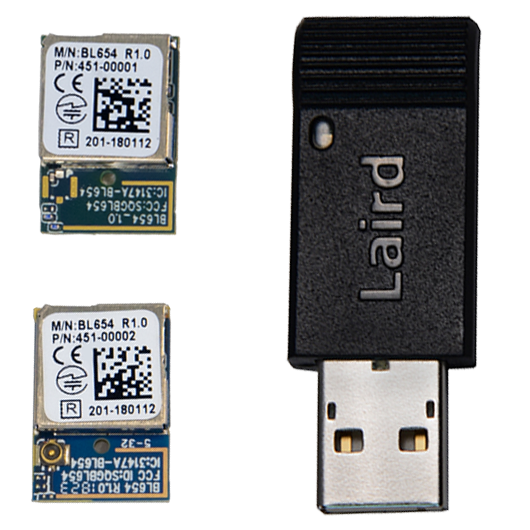
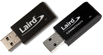
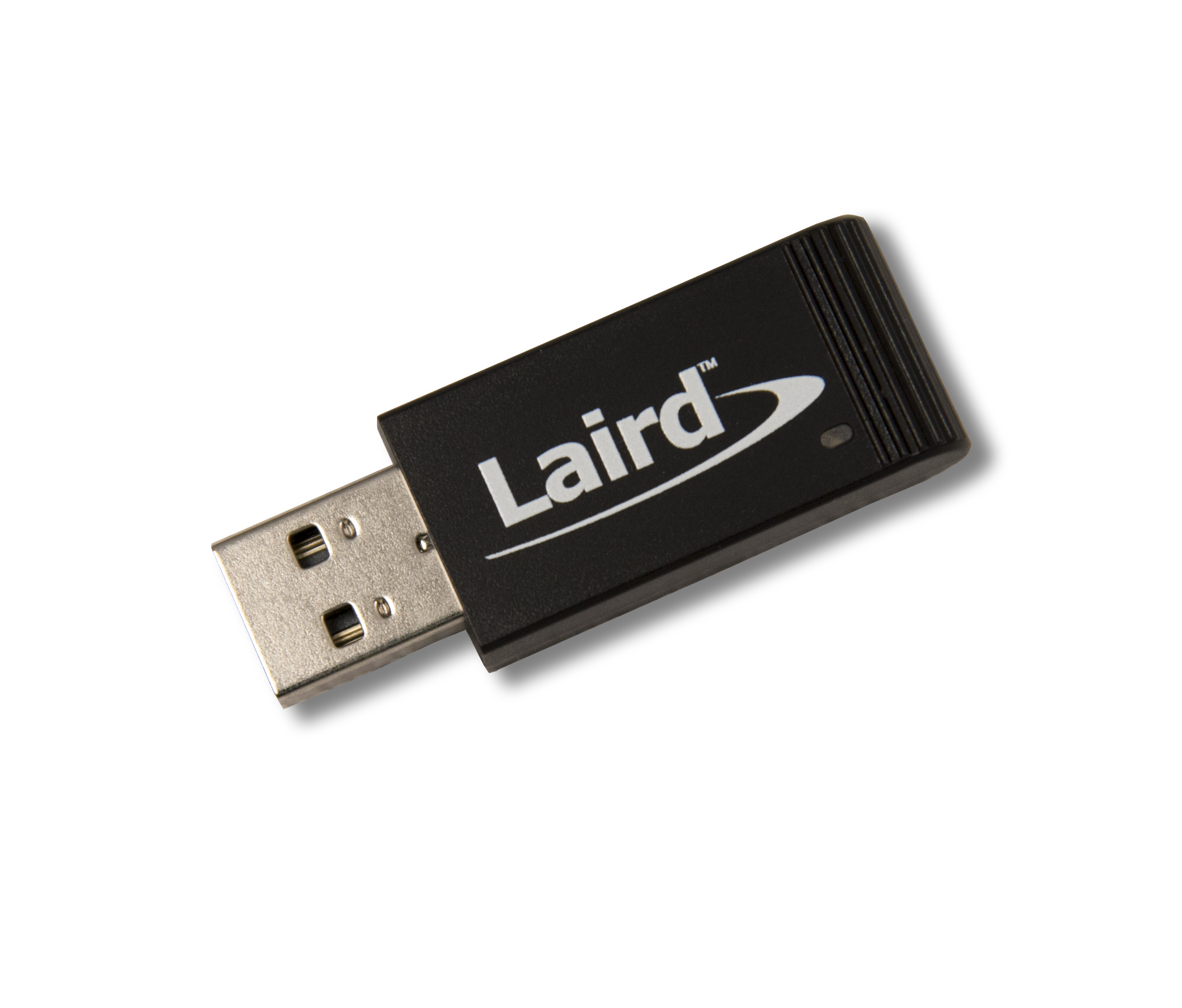
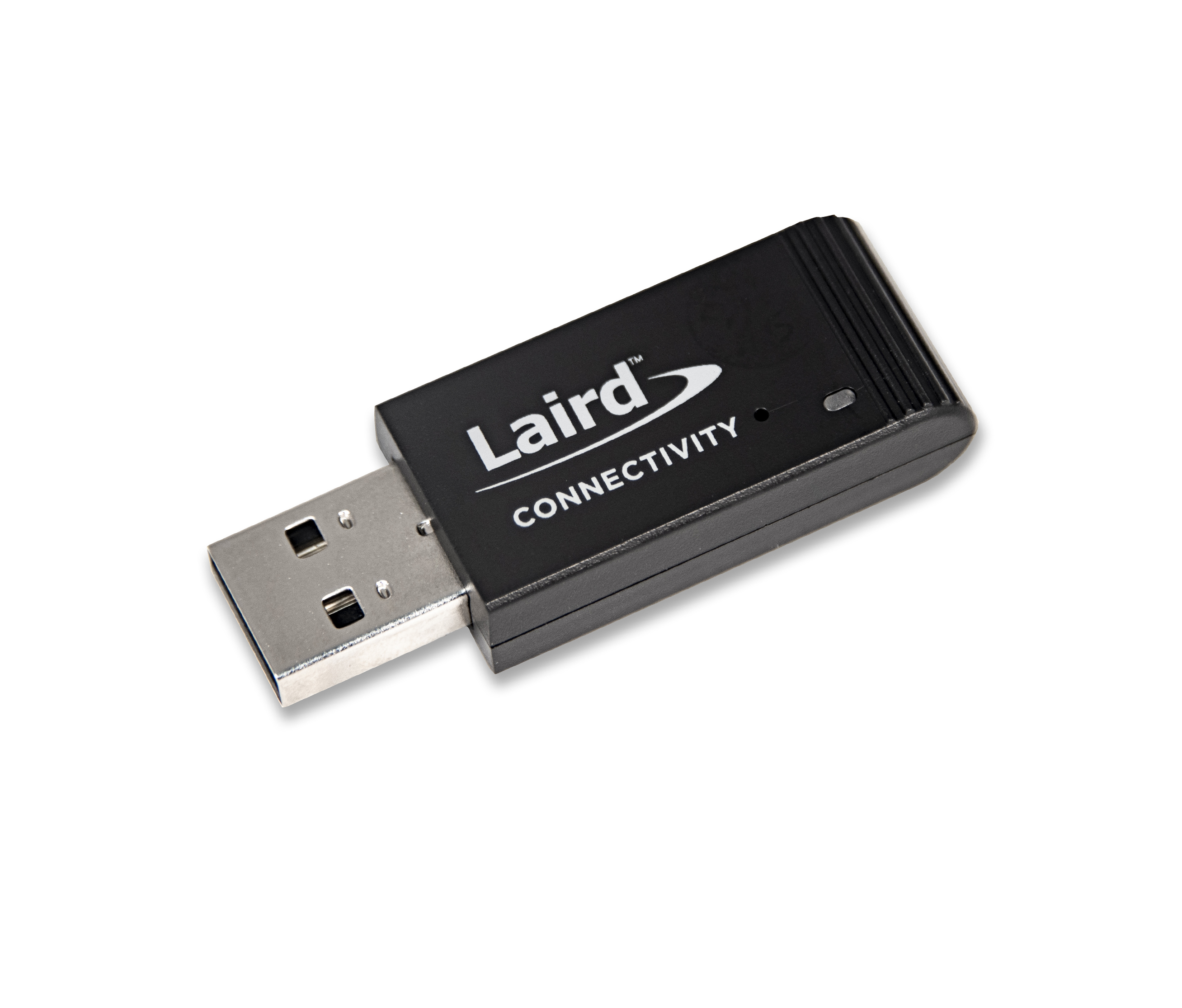
USB Dongle Option - Packaged USB Adapter – bring full Bluetooth 5.3 connectivity to ANY device with a virtual COM port capability
A Kit That Delivers Just What You Need
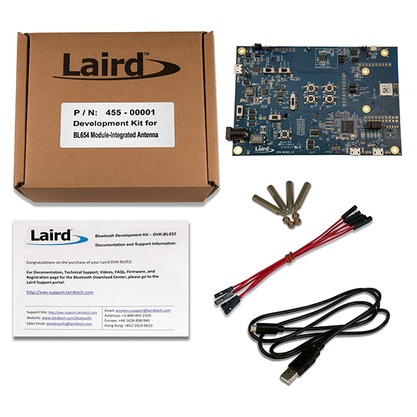
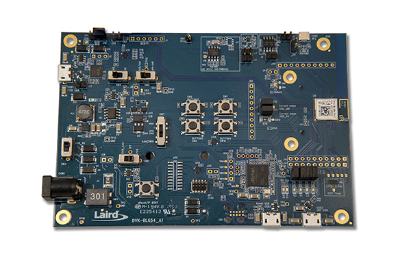
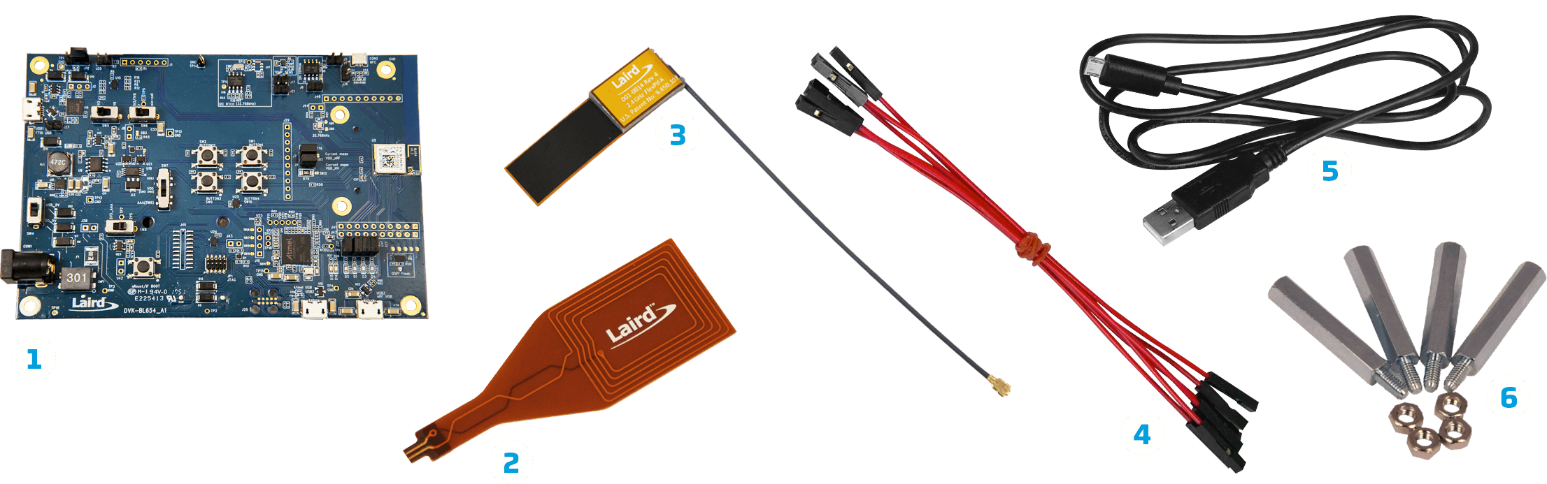
Laird’s BL654 development kits provide a platform for rapid prototyping of BL654 modules. The development boards provide simple, easy-to-use access to the various hardware interfaces and configuration options for the modules. These DVKs are the perfect platform to provide early development testing of BL654 features and functionality.
- DVK Unit
- External NFC Antenna
- FlexPIFA Antenna (455-00002 DVK only)
- Fly Leads (x6)
- USB-A to Micro-USB Cable
- DVK Board Standoffs
Endless Applications
-
/filters:background_color(white)/2024-02/Sensor-Icon1.png)
IoT Devices and Sensors
-
/filters:background_color(white)/2024-02/icon-beacons.png)
Beacons and Proximity Applications
-
/filters:background_color(white)/2024-02/icon-medical-devices.png)
Secure Medical Peripherals
-
/filters:background_color(white)/2024-02/icon-industrial.png)
Industrial Monitoring
Getting Started with Zephyr on the BL652/BL654
The BL652 and BL654 support many development options - software support for Ezurio's smartBASIC, simple AT Command Set, and the Nordic SDK. We've also recently added support for Zephyr RTOS. See the video below for details.
Specifications
| Part Number | Antenna Options | Antenna Type | Bulk or Single | Chipset (Wireless) | Dimension (Height - mm) | Dimension (Length - mm) | Dimension (Width - mm) | Frequency Range (Max) | Frequency Range (Min) | Frequency Range 2 (Max) | Frequency Range 2 (Min) | Logical Interfaces | OS/Software | Product Type | Programming Options | System Architecture | Technology | Type | USB |
|---|---|---|---|---|---|---|---|---|---|---|---|---|---|---|---|---|---|---|---|
 Recommended for New Design (RND) Buy Now | Internal | Bulk - Tape/Reel | Nordic nRF52840 | 2480 MHz | 2402 MHz | 13.56 MHz | 13.56 MHz | Serial, GPIO, ADC, I2C, SPI, PCM, I2S, NFC, PWM, USB | Nordic SDK, smartBASIC, AT Commands, Zephyr | Embedded Module | Hostless | Bluetooth 5.3, Single Mode (BLE), NFC, 802.15.4 / Thread / Zigbee | Module | ||||||
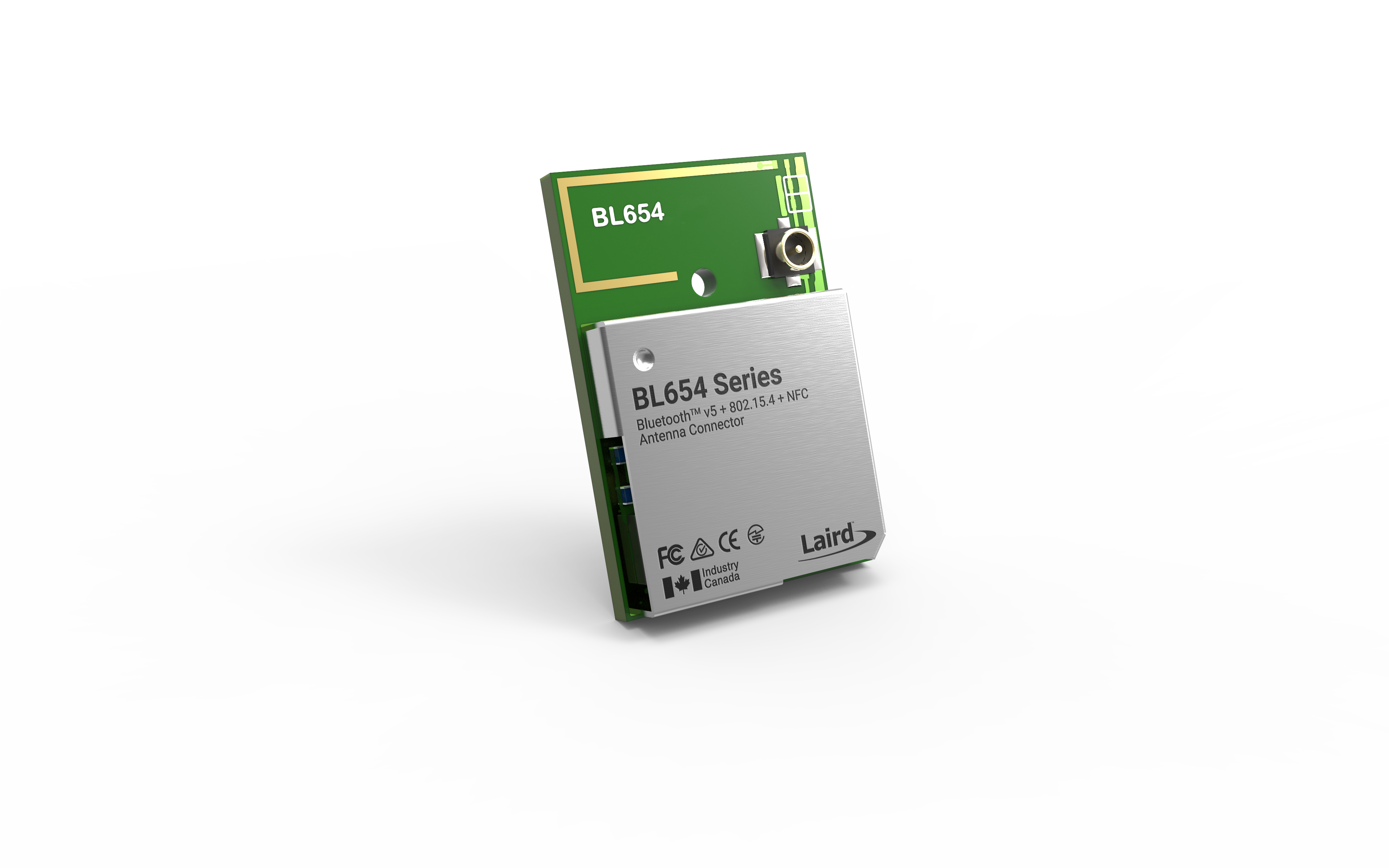
 Recommended for New Design (RND) Buy Now | IPEX MHF4 | External | Bulk - Tape/Reel | Nordic nRF52840 | 2480 MHz | 2402 MHz | 13.56 MHz | 13.56 MHz | UART, GPIO, ADC, I2C, SPI, PCM, I2S, NFC, PWM | UwTerminalX (Windows/Linux/Mac), Nordic SDK, smartBASIC, AT Commands, Zephyr | Embedded Module | Hostless | Bluetooth 5.3, Single Mode (BLE), NFC | Module | |||||
Recommended for New Design (RND) Buy Now | Internal | Bulk - Cut Tape | Nordic nRF52840 | 2480 MHz | 2402 MHz | 13.56 MHz | 13.56 MHz | Serial, GPIO, ADC, I2C, SPI, PCM, I2S, NFC, PWM, USB | Nordic SDK, smartBASIC, AT Commands, Zephyr | Embedded Module | Hostless | Bluetooth 5.3, Single Mode (BLE), NFC, 802.15.4 / Thread / Zigbee | Module | ||||||
Recommended for New Design (RND) Buy Now | IPEX MHF4 | External | Bulk - Cut Tape | Nordic nRF52840 | 2480 MHz | 2402 MHz | 13.56 MHz | 13.56 MHz | Serial, GPIO, ADC, I2C, SPI, PCM, I2S, NFC, PWM, USB | Nordic SDK, smartBASIC, AT Commands, Zephyr | Embedded Module | Hostless | Bluetooth 5.3, Single Mode (BLE), NFC, 802.15.4 / Thread / Zigbee | Module | |||||
 Recommended for New Design (RND) Buy Now | Internal | Single | Nordic nRF52840 | 11 mm | 50.74 mm | 18.39 mm | 2480 MHz | 2402 MHz | 13.56 MHz | 13.56 MHz | Serial (UART) | smartBASIC, AT Commands | USB Adapter | smartBASIC, AT Command Set, (Nordic SDK not supported) | Hostless | Bluetooth 5.3, Single Mode (BLE), 802.15.4 / Thread / Zigbee | Pluggable USB Adapter | FTDI Based - Virtual COM Port | |
 Recommended for New Design (RND) Buy Now | Internal | Single | Nordic nRF52840 | 11 mm | 50.74 mm | 18.39 mm | 2480 MHz | 2402 MHz | 13.56 MHz | 13.56 MHz | Serial (USB) | Nordic SDK, Zephyr | USB Adapter | Zephyr / Nordic SDK | Hostless | Bluetooth 5.3, Single Mode (BLE), 802.15.4 / Thread / Zigbee | Pluggable USB Adapter |
Development Kits
-
/filters:background_color(white)/2019-02/DVK-BL654%20IntAnt%20BoxContents.jpg)
455-00001
Recommended for New Design (RND)Development Kit with Integrated Antenna
Antenna TypeInternalLogical InterfacesSerial, GPIO, ADC, I2C, SPI, PCM, I2S, NFC, PWM, USB -
/filters:background_color(white)/2019-02/DVK-BL654%20ExtAnt%20BoxContents.jpg)
455-00002
Recommended for New Design (RND)Development Kit with FlexPIFA Antenna
Antenna TypeExternalLogical InterfacesSerial, GPIO, ADC, I2C, SPI, PCM, I2S, NFC, PWM, USB -
/filters:background_color(white)/2021-04/453-00062-K1_BoxContents-1200.png)
453-00062-K1
Additional DescriptionUSB-SWD Programming Kit: Includes mainboard, TC2050-IDC Tag Connect cable, 10-pin flat IDC cable, 1.2 m USB cable, and 2-pin jumper
Documentation
Certified Antennas
/filters:background_color(white)/2018-11/mFlexPIFA-standalone-thumb_0.png)
/filters:background_color(white)/2022-05/2.4ghz%20flexpifa.png)
/filters:background_color(white)/2019-03/2-4-ghz-flexnotch-rf-antenna.png)
Do you support any echoing support in the AT Interface app / implementation such as ATE1 & ATE0 for example?
Both ATE1 and ATE0 commands are pretty common in the modem world which would turn on and off the echo mode. In this case, any typed character(s) will be displayed to the screen or terminal – otherwise they are completely suppressed. This behaviour can be very useful for debugging or in some applications. However, there is currently no support for any echoing in our own AT Interface app and implementation. We recommend (if possible) to use a terminal application as an alternative such as UwTerminalX. In PuTTY, Tera Term or RealTerm this can be configured and enabled if needed.
How can the smartBASIC License key be restored if I get "192A - NVO_NVWORM_EXISTS: The WORM segment already exists and cannot be re-created" error when applying the license using AT+LIC command?
The "192A - NVO_NVWORM_EXISTS: The WORM segment already exists and cannot be re-created" error message indicates that a license key has already been written to the module at some point after the firmware was
flashed, likely an incorrect license key. You can verify this by sending the command ATI 49406 which calls the license key programmed
to the module, followed by the ATI 4 to see if "C0FFEE" appears as the last three bytes of the response returned.
Because
this setting is one time writable in the firmware, if an incorrect license key
has been written, it will be necessary to first erase the flash completely on the module. This can be done using Nordic's nRF Connect for Desktop Programmer
application:
1)
Obtain the correct License Key hash from our Support Team
by connecting the DVK to your PC via the UART interface (USB 1 of the DVK) and getting the
full MAC Address of the module by calling ATI 14. Provide the response to the support team member
so the correct key can be generated.
2)
Connect the DVK to your PC via the SWD (JTAG) interface
(USB2 of the DVK).
3)
Open the Programmer
Application in nRF Connect for Desktop.
4)
Select the Device in the Programmer application.
5)
Select "Erase all".
6)
Reflash the smartBASIC firmware file via the SWD (JTAG) Interface.
7)
Call ATI 49406 to confirm the license key has been erased (should return 00).
8)
Send the AT+LIC "[License Key generated by FAE]"
command to apply the correct smartBASIC license key.
9)
Call ATI 4 - confirm C0FFEE does not appear in the MAC
Address of the module.
When working with AT Interface firmware, what is the correct syntax to use the AT+LSCN command when not wanting to use all the optional parameters?
As
per the AT Interface User Guide, the AT+LSCN
AT+LSCN
Therefore,
the correct syntax for AT+LSCN without using all optional parameters would be
to leave the unused parameters blank (not a "0", just blank) while still dividing
each of the optional parameters using commas. For example, if the only
parameter required is to configure it the scan type (last parameter) to enable
scanning for 1M and Coded PHY (256k) with extended advertisements you would use
the following syntax:
AT+LSCN ,,,7
Please see the AT Interface User Guide for the module you
are working with for more information.
Lyra
Series Modules – AT Interface User Guide
When attempting to enable the external crystal within the smartBASIC code using BleConfigHfClock(1), why does it not change to high speed when calling SYSINFO(2082)?
It is
important to note there are two clock sources, a High Frequency (HF) Clock
source, which is used for clocking the system, and a Low Frequency (LF) Clock
which is primarily used for Sleep Mode. Each of these have options of using an
internal oscillator on the chip, or the specified crystal.
The external 32 MHz crystal for the HF Clock is included on the
module, while the external 32 KHz crystal is an optional LF Clock source which
is NOT included on the module. The optional crystal for the LF Clock source
provides improved protocol timing and helps with radio power consumption when
the radio is in standby doze/deep sleep, by reducing the time that the Rx
window needs to be open.
The BleConfigHfClock() function
within the smartBASIC application is used to select the High Frequency Clock, which is the system clock.
This is the 32MHz crystal, and it can be selected using this BleConfigHfClock()
function.
This is different than the optional external 32kHz Crystal,
which is used as the Low Frequency Clock source. This crystal is typically used
for sleep modes. This can only be selected using the AT+CFG 210 and
cannot be configured within the smartBASIC application. SysInfo 2082 is used to return the Low Frequency
Clock configuration, therefore, it is not affiliated with the High Frequency
Clock setting.
How do you exit Autorun Mode, to enable updating a smartBASIC application OTA or via the UART?
To be able to exit Autorun Mode it is
necessary to include an option in the smartBASIC code, prior to loading it to
the module, that provides a way to exit the application, or have access to the
nAutoRun pin. The options are explained below for UART and OTA methods for
exiting Autorun Mode.
UART Methods:
1) Provided access is available to the nAutoRun pin,
pull the nAutorun pin HIGH to move the module from nAutorun mode to Development
mode. Once this pin is pulled high and the module is reset it should enter into
Interactive Command mode and it should be possible to erase the file system,
using AT&F1 and load a new smartBASIC application over the UART.
2) Have a way to exit the application, via a command or
pin setting, using Endfunc 0. If Waitevent is the last statement in the
application, and a function triggered by the command or pin change returns
"Endfunc 0", then the module will exit the application and return to
Interactive Command mode. Once the module returns to Interactive Command mode,
the file system can be erased with AT&F1, and the updated application can
then be loaded.
Over-the-Air smartBASIC application loading requires
control of the vSP pin. To enter into OTA mode, it is necessary to pull the vSP
pin of the BL65x module high, while the nAutorun pin is held low. This places
the module in vSP-Command Mode, as opposed to vSP-Bridge mode, as explained in
the "Command and Bridge Mode Operation" section of the matching
smartBASIC Extensions User Guide for the module (see links below).
BL654/BL654PA smartBASIC Extensions
Guide v29.5.7.2
User Guide - BL653
and BL653µ smartBASIC Extensions Guide v30.2.3.0
User Guide - BL652
smartBASIC Extensions v28.10.7.2
However, if an $autorun$ application is loaded to the
module when the vSP pin is pulled high it will just run the application, in
which case the one of the following methods can be used to enable exiting the
application and erase the file system so that an updated application can be
loaded.
OTA Methods:
1) Invoke the EraseFileSystem() function in the
smartBASIC application. This function is used to erase the flash file
system which contains the application that invoked this function, if and only
if, the vSP input pin is pulled high. Given that SIO2 is high, after
erasing the file system, the module resets and reboots into command mode with
the virtual serial port service enabled (vSP-Command Mode), and the
application can then be loaded following the OTA method.
2) Have a way to exit the application within the
smartBASIC code, via a command or pin setting, using Endfunc 0. If “Waitevent” is
the last statement in the application, and a function triggered by the command
or pin change returns "Endfunc 0", then the module will exit the
application and return to Interactive Command mode. Once the module returns to
Interactive Command mode, the file system can be erased with AT&F1, and the
updated application can then be loaded.
For convenience, a list of the nAutoRun pins/SIO and
vSP pins/SIO for all BL65x modules is provided below. These can also be found
in the Datasheet for the specified module.
| BL65x nAutoRun and vSP pins | ||
| Module | nAutoRun Pin | SIO |
vSP Pin |SIO |
| BL654PA | Pin 5 SIO_35 |
Pin 50 SIO_02 |
| BL654 | Pin
5 SIO_35 |
Pin
50 SIO_02 |
| BL653 | Pin
34 SIO_35 |
Pin
50 SIO_02 |
| BL653u | Pin
34 SIO_35 |
Pin
37 SIO_02 |
| BL652 | Pin
28 SIO_13 |
Pin
23 SIO_02 |
How do I launch menuconfig for Zephyr?
If you would like to launch "menuconfig" for your Zephyr build, add "-t menuconfig" to the end of your build command.
For example:
west build -p -b mg100 -d ble_gateway_dm_firmware/build/mg100 ble_gateway_dm_firmware -- -DAPP_TYPE=mqtt -t menuconfig
For more information:
Interactive Kconfig interfaces — Zephyr Project Documentation
How can I implement an HCI interface for the IG60-BL654?
An HCI interface can be implemented in lieu of using smartBASIC to communicate with / program the BL654 in Laird's IG60.
To achieve this, build the hci_uart example for BL654_DVK.
Bluetooth: HCI UART — Zephyr Project Documentation
Direct the output to a folder, for example:
west build -b bl654_dvk samples/bluetooth/hci_uart --pristine -d my_firmware
Download Ubutil—
Linux:
UBUtil Firmware Upgrade Generation Utility v1.0 – Linux / MAC | Ezurio
Windows:
UBUtil Firmware Upgrade Generation Utility v1.0 – Windows | Ezurio
Follow these instructions to create a .UBU:
Firmware Programming Guide (lairdconnect.com)
TLDR:
Copy the zephyr.hex from the "my_firmware" directory in Zephyr.
./UBUtil --create-key hci_uart.pem
./UBUtil --application-key-file hci_uart.pem --a0-version 1 --a0-compressed --a0-target 0 --a0-startaddress 0x1000 --a0-filetype 1 --a0-filename zephyr.hex --a0-keytype 1 --append-pub-key --output zephyr.hex --ubu-output hci_uart.ubu --ubu-platform 5ECB654F --ubu-flash-size 2097152 --ubu-sector-size 4096 --ubu-base-address 0 --ubu-align-length 4
Copy the .ubu to the IG60.
With the file on the gateway execute the following command:
- btpa_firmware_loader.py /dev/ttyS2 115200 hci_uart.ubu BL654
Reboot the system, then check /sys/class/bluetooth for hci0. If this sysfs node is present you've successfully created the HCI interface.
Does the BL5340, BL5340PA, BL65x and Lyra BLE modules include the DC-DC LC filters on the module?
Yes, all BT modules
include the needed LC filter components required for DC-DC Converter operation.
Lyra P and Lyra S modules include a 2.2uH inductor on VREGSW output and 4.7uF capacitor to ground.
The nRF528xx used on the BL65x modules use two voltage regulators, REG0 and REG1. In Normal Voltage mode only REG1 is enabled. In High Voltage mode both REG1 and REG0 are enabled. The BL65x modules include 10uH and 15nH inductors on DCC output and 1.0uF capacitor to ground on REG1. REG0 includes a 10uH inductor on DCCH output and 4.7uF cap to ground.
Note: The BL651 module uses the nRF52810
which uses a single voltage regulator. The BL651 includes 10uH and 15nH
inductors on DCC output and 1.0uF capacitor to ground.
The nRF5340 used on the BL5340 and BL5340PA modules uses four voltage regulators, Main Voltage Regulator, Radio Voltage Regulator, High Voltage Regulator and a USB Regulator. In Normal Voltage mode the Main Voltage and Radio regulators are enabled while the High Voltage Regulator is disabled. In High Voltage mode the High Voltage regulator is enabled along with the Main Voltage and Radio regulators. The BL5340 module includes a 10uH inductor on the DCC outputs and 1uF capacitor to ground on the Main Voltage and Radio Voltage regulators. The High Voltage regulator includes a 10uH inductor on the DCCH output and 2.2uF capacitor to ground. The USB regulator uses an LDO only an no DC-DC filter components are needed.
What is the Project Zephyr Discord?
There's a Zephyr RTOS Discord channel. This is a great place to ask questions and have them answered by the engineers who wrote the software. There's even a channel for HL7800!
How can I change the 32.768KHz Low Power Clock Source using nRF Connect SDK v2.x?
With nRF Connect SDK v2.0.0 and later only VS Code is made
available as an IDE as VS Code provides many features including both Command
Line Interface (CLI) and Graphical User Interface (GUI) in one environment.
Prior to nRF Connect SDK, the 32.768KHz source in nRF5 SDK applications defaulted to using the external crystal oscillator. The BL65x DVK’s populate an external 32.768KHz crystal but it is not connected via open solder bridges. Therefore, either the solder bridges need to be shorted to make the external crystal connection or change the clock source to internal RC Oscillator via the sdk_config.h file.
With nRF Connect SDK the correct 32KHz clock source is selected depending on the EVK. For BL654 DVK examples are built using internal RC oscillator. On BL5340 DVK the external crystal oscillator is selected as the DVK does close the solder bridge pads.
If the 32KHz clock source needs to be changed an application can change accordingly in the prj.conf file of the project. The following direct dependencies need to be added to prj.conf to override the default clock configuration.
External Crystal Oscillator and accuracy selection:
CONFIG_CLOCK_CONTROL_NRF_K32SRC_50PPM=y
Internal RC Oscillator and accuracy selection:
CONFIG_CLOCK_CONTROL_NRF_K32SRC_RC=y
CONFIG_CLOCK_CONTROL_NRF_K32SRC_500PPM=y
Kconfig dependencies can be found:
https://developer.nordicsemi.com/nRF_Connect_SDK/doc/2.3.0/kconfig/index.html
How is a static passkey configured for use in AT Interface Application/Firmware?
Lyra modules must be preloaded with AT Interface firmware, while BL65x modules must be updated to the most current smartBASIC firmware version and programmed with the AT Interface smartBASIC sample application in order to use any AT Interface commands.
To configure a static passkey using AT Interface it is necessary to ensure that the I/O capability of the modules will result in Passkey Entry authentication (per the Bluetooth SIG's IO Capabilities mapping). The Lyra or BL65x module must be configured with the I/O Capability set to Keyboard Only (2) or Keyboard + Display (4), via S Register 107, using the command, ATS 107=x, where x=2 for Keyboard Only or x=4 for Keyboard + Display.
Then the "AT+PKEY " command can be used to issue a static passkey to the underlying stack for use during a pairing procedure in future connections. The passkey must be a 6-digit integer in the range of 000000 – 999999.
The pairing will still use LESC Diffie-Hellman based exchanges. If a randomly generated number is used for the passkey the static passkey will be used.
Note: Pairing using a pre-programmed passkey makes pairing vulnerable to MITM attacks.
For more information on AT Interface configurations please reference the AT Interface User Guide for the specified module series.
Is the command used to set a static passkey with AT Interface firmware, AT+PKEY, persistent through a reset or power-cycle?
The AT+PKEY nnnnnn command, used by AT Interface to configure a static passkey, is an on-the-fly command and will not be persistent through a power-cycle/reset. Only S Register settings, using the ATS & AT%S commands, can be saved using AT&W followed by ATZ. All other AT commands are on-the-fly.
NOTE: Using a static, pre-programmed, passkey makes pairing vulnerable to MITM attacks.
For additional information on configuring a static passkey with AT Interface please refer to the appropriate AT Interface User Guide for the Ezurio module you are working with linked below:
User Guide - AT Interface Application - Lyra Series
Using STTY with the USB-SWD
These instructions are intended for Linux or Macintosh OS. They may work using WSL, Cigwin, or other bash style terminals in Windows although this is untested.
It may be desired to communicate with a device attached to the USB-SWD without terminal emulation, I.E. Picocom, Screen, Putty. This can be useful for writing bash scripts, or if you're using Zephyr's "west flash" and would like a quick way to check your output.
- Verify you have the program "stty" available using the command "which stty", if this does not return a value you will need to install it. Fortunately "stty" generally comes standard with Linux and MacOS.
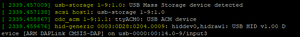
- Identify your serial device. This can be done using the command "dmesg -w" then connecting the USB-SWD. You will see output like this (In Linux).
- (Optional) Assign the device name to a variable, for example "DEVICE=/dev/ttyACM0".
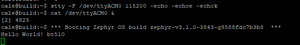
- Configure "stty" to talk with the device "stty -F $DEVICE 115200 -echo -echoe -echok"
- To see output from the device execute "cat $DEVICE &". This will send serial communication from the device to Linux's standard output. The "&" is to run this program in the background.
- Now press the reset button on the USB-SWD, you should see the output from your device. In this example the Zephyr "Hello World" example has been flashed to a BT510.
- (Optional) if you would like to send commands back to the device you can use "echo" or add an argument to your shell, "foo() { echo -n -e "$1\r" > $DEVICE; }". Now commands can be issued directly from the command line, for example "foo "my_command"" will send the string "my_command" to the device.
Do the NFC traces need to be controlled differential impedance between NFC1 and NFC2?
The NFC track does not need to be routed with a controlled differential impedance. The NFC antenna is different from the BLE antenna as it's differential and not 50 Ohm (each track is 50 Ohm single ended). Also, the frequency is very low, so the exact impedance doesn't matter as much. The inductance in the antenna is what matters for the NFC antenna. Since the antenna is differential, it's better to use a two-pin connection instead of U.FL which is a single ended connection.
The inductance of the antenna together with the NFC antenna tuning capacitors forms a resonant circuit that is tuned to the NFC frequency, 13.56 MHz. Any change in the connection wires to the antenna can be compensated with the tuning caps.
When working with AT Interface why am I not able to get the module down to 2uA low power mode documented in the Lower Power Mode Application Note?
The Low Power Mode referenced in the following Application Notes are based on running the lp.low.power.deep.sleep.sb sample application which is written specifically for achieving the lowest possible power state of the BL65x module. All of the LEDs on the DVK-BL65x are set to digital out low, the temperature sensor is disabled, and the UART is closed before going into the waitevent. When running the sample application referenced in the document the BL65x module will enter into enter Deep Sleep or Low Power Doze Mode (at waitevent) and achieve the stated low power levels.
Low Power Modes - BL654 v1 1.pdf
Application Note - Low Power Modes - BL654PA
Application Note - BL653 Low Power Modes
Application Note - BL653µ Series - Low Power Modes
BL652 Low Power Modes.pdf
However, if you reference section 3.8 of the AT Interface User Guide you will better understand the nature of the AT Interface application, and why the current consumption is higher even when you are sitting at a waitevent, not entering commands. The Lpuart variant of the AT.Interface smartBASIC application ($autorun$.AT.interface.BL65x.lpuart.sb) can be used to operate the module in doze mode (with the UART closed most of the time) so that the total current consumption can be as low as sub 10 microamps.
Can I pair in vSP Mode with AT Interface Application
Is it possible to bond devices in vSP mode when using the AT Interface application.
In
order to enable the devices to pair and bond in vSP mode, when working
with the AT Interface sample application, you must make the initial
connection in non-vSP mode, using the command, AT+LCON
Once the devices have connected you can pair using the command, AT+PAIR hdlx
command to pair. The pairing will automatically be stored in the
bonding database., Then disconnect the devices and you can now reconnect
in vSP mode using the command ATD
See example with comments following // below:
ati 0                                                  //Calls Device name
BL654
OK

ati 3                                                //Calls the firmware version on the module
29.5.7.2
OK
ati 4                                                       //Calls the BT ADDR of the module
01F192652D3FB1
OK
ati 2009 //Calls number of devices in Bonding Database
0
OK
at+lcon 01D1C4A981E5E7                   //Connects in non-vsp mode with specified BT ADDR
connect 1,01D1C4A981E5E7,15000,6000000,0
OK

at+pair 1                                                //Pairs with connection handle created when devices connected
OK
encrypt 1
PI:1, 0, 0, 5, 3
at+ldsc 1                                                  //Disconnects the devices
OK
discon 1,22
ati 2009                                                  //Confirms one device is stored in the bonding database
1
OK
at+bndt 01D1C4A981E5E7                //Confirms the BT_ADDR specified is bonded and stored in database
1,1,01D1C4A981E5E7
OK

atd 01D1C4A981E5E7                     //Connects in vSP Mode (encrypted)
ENCRYPT

CONNECT 0, 01D1C4A981E5E7,15000,6000000,0
Do I have to use hardware RTS/CTS handshake with the Laird BLE modules?
We advice to use RTS/CTS hardware handshake on all of our SmartBASIC modules. This will avoid UART buffer overflow and loss of data.
However, if e.g. no hardware handshake signals are available on your host system, you might want to try
- Using XON/XOFF software handshake instead.
- Use not handshake at all but lowering the baud rate significantly. This can prevent buffer overflow to a certain extend but actually depends on your particular application and whether other tasks active on the module would consume processing power.
Make sure to always use the latest SmartBASIC firmware version and check the SmartBASIC and module documentation.
If not using SmartBASIC but implementing an own application with nRF Connect SDK or Zephyr, you are free to not use hardware handshake and implement a proper protocol to avoid buffer overflow on application side.
What are the hardware design recommendations for the BL653/BL654 USB interface if not used?
The BL653/BL654 provides an USB 2.0 full-speed (12 Mbps) interface which is compliant to the Universal Serial Bus Specification Revision 2.0. We recommend connecting VBUS to GND and leaving both D+ and D- data pins unconnected if developers do not need or want to implement the USB interface in their hardware designs. Please note that smartBASIC does not support USB functionality, so for software and application development you would need to either use Zephyr or the Nordic SDK.
Why does my BLE module have an extra 01 in front of its MAC address?
For example in SmartBasic Interactive mode
ati 4
10 4 01 EFA44957769F
00
BLE devices can have multiple mac addresses and if the mac address begins 01 as above it signifies it is a random static address which is assigned during manufacture. While its random nature means its not unique the number of possible random static addresses is 2^(48-2)-2 a very large number so it is very unlikely you will ever see a duplicate, let alone in the same place at the same time.
Other MAC address types include
- 00 IEEE assigned public address, the same as used by BT classic devices
- 01 Random static, generated at manufacture
- 02 Random private resolvable with IRK. resolvable by other devices already known
- 03 Random private non resolvable
To address privacy concerns, there are four types of Bluetooth addresses in a BLE device which can change as often as required. For example, an iPhone regularly changes its BLE Bluetooth address and it always exposes only its resolvable random address. This feature is known as LE privacy. It allows the Bluetooth address within advertising packets to be replaced with a random value that can change at different time intervals. Malicious devices are not able to track your device as it actually looks like a series of different devices. To manage this, the usual six-octet Bluetooth address is qualified on-air by a single bit which qualifies the Bluetooth address as public or random: ▪ Public – The format is as defined by the IEEE organisation. ▪ Random – The format can be up to three types and this qualification is done using the upper two bits of the most significant byte of the random Bluetooth address.
On Ezurio SmartBasic module, the address type can be set using the function BleSetAddressTypeEx(). On the other hand, Sysinfo$(4) can be used to retrieve the Bluetooth address if it is public or random static. Due to LE privacy 1.2, if the address type is random resolvable or random non-resolvable, it cannot be retrieved by the application layer since it is fully controlled by the baseband layer.
Note: The Bluetooth address portion in smartBASIC is always in big endian format. If you sniff on-air packets, the same six packets appear in little endian format, hence reverse order – and you do not see seven bytes, but a bit in the packet somewhere which specifies it to be public or random.
Does laird Connectivity support Nordic Enhanced Shock Burst (ESB)?
Yes, but software support should be sought direct from the Nordic Devzone as from Lairds point of view we provide only the hardware not the protocol.
Enhanced Shockburst (ESB) is a proprietary simple packet protocol for use in the Nordic modules. It is simple and easy to use and can give very low latency applications compared to BLE.
However, there is no encryption employed in ESB and ESB operates on a single frequency channel so there is no frequency immunity. You can implement your own encryption in upper layers though.
Also see Gazell (GZLL), which is another proprietary protocol from Nordic that builds on ESB.
Can I stop the BL65x firmware upgrade batch file from closing?
Smartbasic firmware is normally flashed to a BL65x module using a Windows batch file but the batch file command window will automatically close on completion. To keep this window open, to view what has happened add the following to the end of the batch file in question.
cmd /k
example below
.
.
.
:pauseend
if "%1" == "nopause" goto :end
pause
:end
cmd /k
Should I use nRFConnect SDK or nRF5 SDK with the Laird BL65x modules?
Nordic nRFConnect SDK, also known as NCS is based on the Zephyr RTOS with support for Laird modules based on nRF52 and nRF53
Nordic nRF5 SDK is a legacy bare metal SDK with support for Laird modules based on nRF51 and nRF52
You can choose either SDK but need to know that nRF5 SDK will not be supporting new features going forward. So if starting a new BL65x or BL5340 project then it is recomended to choose nRFConnect SDK.
See nRF Connect SDK and nRF5 SDK statement - Blogs - Nordic Blog - Nordic DevZone (nordicsemi.com) for more details
Do you support Bluetooth features like BLE Mesh, AoA (Angle of Arrival) and/or Angle of Departure (AoD) in your own AT Command Set Interface implementation?
No. There is no software support for BLE Mesh, AoA (Angle of Arrival) and Angle of Departure (AoD) in our current AT Command Set Interface implementation. Please feel free to build and develop your own BLE Mesh, AoA or AoD application in C by using the Bluetooth SDK and tools from Silicon Labs. In this case, as a starting point, we highly recommend the Simplicity Studio 5 IDE which offers a rich set / collection of example projects and templates.
Bluetooth Mesh is a wireless mesh topology and standard which enables many-to-many (m:m) device communication for an enormous number of local BLE devices. It supports large-scale node networks without the need of an ordinary BLE gateway infrastructure. Refer to https://www.lairdconnect.com/making-bluetooth-mesh-simple and https://www.bluetooth.com/learn-about-bluetooth/recent-enhancements/mesh for additional information.
Angle of Arrival (AoA) and Angle of Departure (AoD) are two concepts for location positioning and direction finding. Without going into too much detail and to keep things very simple: One of the two BLE devices must have at least two antennas or more, so that the data received from those antennas then can be used to identify the direction and angular position of the location where the Bluetooth signals come from. Please find further information available at https://www.lairdconnect.com/resources/blog/magic-bluetooth-aoaaod-direction-finding and https://www.bluetooth.com/blog/new-aoa-aod-bluetooth-capabilities.
Why is SWDIO/SWCLK shorted to GND on my board?
According to the Nordic DevZone there are mainly two potential issues leading to a short on one of the SWD signals:
- ESD issue, likely when connecting an SWD programmer to the SWD signals.
- Connecting an SWD programmer while the target board is not connected to supply voltage.
Please make sure proper ESD precautions are taken into account (ESD wrist-strap, ESD base/mat) as well as make sure to first connect the supply voltage and then the SWD programmer.
Is it possible to clear or reset a table in smartBASIC?
Tables provide associative array (or in other words lookup type) functionality within smartBASIC programs. They are typically used to allow lookup features to be implemented efficiently so that, for example, parsers can be implemented.
There does not exist a function to delete particular entries from a table, but it's possible to overwrite existing elements with TableAdd(). TableLookup() will then return the new element. However, the elements are not actually being overwritten, but marked deleted and added newly to the table, hence the table memory consumption will increase.
To fully clear a table it's possible to simply call TableInit() again.
Can I read a file in SmartBASIC Interactive Mode with an AT Command?
While it's possible to open/write/close files from SmartBASIC Interactive Mode (AT+FOW, FWR, FCL) to e.g., enter configuration information for a SmartBASIC application, there is no AT command available to display the content of a file from the flash file system.
A workaround would be adding another SmartBASIC application to a device which can be started in Interactive Mode (AT+RUN or just the name) and opens the (config) file and prints the content to the console. Below is an example application.
How many concurrent connections I can get with BL654 loaded with AT Commands interface app code?
The default maximum numbers of BLE connection allowed with AT Commands is 8.
Assuming you are working with the AT Command interface application version 4.04 and Library version 5.02 or newer, you can reach until 16 concurrent BLE connections through non-VSP mode:
To do so, you'll first need to set up your BL654 to non-VSP mode via S Register 100 (Start-up Flags) then increase the maximum allowable concurrent connections within S Register 126 (Max Connections as Master/Central) as follows:
You'll then be able to connect to until 15 BLE devices as master (AT+LCON) plus 1 as slave (AT+LADV) as follows:
Please note that multiple connections means sharing bandwidth where latency and throughput will be significantly impacted.
How can I interface with a BT510 without the Mobile App?
|
The BT510 is an event driven BLE multi-sensors which is capable of measuring temperature, open/close magnet and motion detection. There is basically two ways to get data from it:
While the BT510 as been especially designed to transfer data via BLE advertisements, you can also use BLE connection to retrieve data. It's worth mentioning that preliminary intended use of BLE connection with the BT510 is for configuration (usually during commissioning process on the field). As exposed into the Sentrius™ BT510 User Guide section 4.2, the BT510 make use of BLE Virtual Serial Port (VSP) service. The BL654 is BLE v5.1 module which embeds an nRF52840 chipset from Nordic. Ezurio developed smartBASIC, an event driven programming language that sits on top of Nordic SDK. Its most famous software/feature is the AT Commands Interface where you can drive a BLE module through UART with using batch of intuitive commands. As part of IoT applications that involve to interact with a BT510 via BLE through a BL654 loaded with AT Command Interface, it can be useful to know the steps to get the BL654 connected to the BT510. Because the BT510 GATT table is protected by a pairing process which involve static passkey (123456), it's important to change BL654 IOCAP in first instance to allow a Passkey entry procedure during pairing/bonding process. On the BL654 side you'll need to follow the procedure below with AT Commands :
Now that both devices are connected with VSP mode, you can write JSON commands to send over BL654 UART in order to configure the BT510 as you like. For more information on JSON spec, you can have a look here : https://www.jsonrpc.org/specification A typical AT Commands session could look like this, where 01C630157769EE is a BT510 BLE Mac Address: ATS 107=4 OK AT&W OK ATZ OK AT+LCON 01C630157769EE connect 1,01C630157769EE,15000,6000000,0 AT+PAIR 1 OK passkey? 1 AT+PRSP 1,123456 encrypt 1 AT+LDSC 1 discon 1,22 // BL654 is now bonded to BT510, VSP connection can be made. ATD 01C630157769EE ENCRYPT CONNECT 0,01C630157769EE,15000,6000000,0 |
Can I load OTA application code into my BL654 USB Dongle P/N 451-00003?
To be able to load an application code Over the Air into a BL654, you need to enter into Virtual Serial Port Command mode. The only way to enter into this mode is to have access to the VSP pin (SIO_02) and pull it to VCC.
The BL654 USB Dongle P/N 451-00003 doesn't expose VSP pin which is tied to the ground internally. There is hence no way to enter into Virtual Serial Port Command mode and to load an application code Over the Air on that product.
Can I use the BL654 USB Dongle as USB HCI Bluetooth device?
There exist two variants of the BL654 dongle:
- 451-00003 is the SmartBASIC driven version which uses an FTDI USB UART converter for USB connection.
- 451-00004 is the Nordic version which leverages the nRF52840 native USB device interface.
Whereas the SmartBASIC version cannot be used anything different than a virtual serial port device from a USB perspective, the Nordic version could be programmed for different USB device classes.
The Zephyr project provides various sample application projects including a Bluetooth usb_hci project. Since the BL654 USB Nordic dongle is a supported board in Zephyr it is possible to compile and load the usb_hci project into the dongle. After doing so, the dongle will operate as a Bluetooth HCI device and enumerate on USB accordlingly. Please follow the general build instructions for Zephyr and the programming/flashing instructions for the BL654 USB dongle.
Does the BL65x or BL5430 support Matter?
Matter can be supported on the BL5340 (nRF52840) and the BL654 when using the Nordic nRF Connect SDK. However, due to the memory requirements of Matter it can not be used on the BL653, BL652 nor the BL651 given their flash and RAM memory footprint.The BL653 (nRF52833) has 512K of Flash and 128K of RAM and BL652 and BL651 has less than that.
There are instructions on how to reduce the memory footprint for Matter in the documentation on the nRF Connect SDK Main branch, Memory footprint optimization » Matter, but even using this you will not be able to get it down to a size fitting on the nRF52833. With the steps from the optimization page with the light bulb sample the size was reduced to approximately 730 kB of flash and 170 kB of RAM when building for nRF52840, which is still way too high for the nRF52833. Additionally, there are possibilities that the Matter flash usage will grow more before the official release, as more bug fixes and things from the Matter specification will be added.
Why can’t I Re-open the UART when it closes when running AT Interface LPUART App?
The LPUART AT Interface app allows users to close down the UART port when entering low power Doze mode for additional power savings. The UART when it is open can consume as much as 350uA. The AT Interface LPUART app provides a cross-compile switch that allows the UART to close most of the time when there is no activity and the Tx/Rx buffers are empty. A “Keep UART Open” is implemented by using a GPIO that when low allows the UART to close after a low power operation timer has expired. When this Keep UART Open GPIO signal is high the UART will not close automatically.
The AT Interface Application sets the default GPIO used for this function to SIO_24. An application can chose any pin other than the default by writing the desired SIO port number to Sreg 109.
The BL65x EVK connects SIO_24 to Button 3. However, if running the AT Interface LPUART application on the EVK the UART will close automatically as soon as the low power timer expires (default set to 5 seconds). The UART can not be re-opened in the case. To reduce power the application configures the Keep UART Open GPIO to input pulldown. However, to operate properly Button 3 when pressed will pull the signal to ground which results in an Event interrupt. Since the GPIO uses an input pulldown it is already low and no Event occurs leaving the UART closed.
A simple change in $LIB$.AT.interface can be made to configure Keep UART Open GPIO to input pullup. This keeps the GPIO high at all times and the UART open. When Button 3 is pressed long enough for the low power time to expire the UART is closed. To re-open the UART Button 3 is pressed again which causes an Event which will re-open the UART.
Change the following line in InitGpio() function in $LIB$.AT.interface:
From:
rc = GpioSetFunc(vspCmdModePin, SIOTYPE_DIN, INPUT_PULL_DOWN)
To:
rc = GpioSetFunc(vspCmdModePin, SIOTYPE_DIN, INPUT_PULL_UP)
Also to change the functionality so once the UART is closed is remains closed until the next button press also change the next line in InitGpio().
From:
rc = GpioAssignEvent(0, vspCmdModePin, 0)
To:
rc = GpioAssignEvent(0, vspCmdModePin, 1)
How to avoid/disable module reset on UART break with SmartBASIC?
The default behaviour of the SmartBASIC driven BLE modules is entering deep sleep mode when a UART break condition is being detected and wake up through reset when released. While this is a convenient way to reset a module without having access to the reset line e.g., during development when connected with UwTerminalX, it might be unintended in the final application environment.
For the more recent SmartBASIC BLE modules like BL652, BL653, BL654, BL654PA the behaviour when detecting a UART break is configurable when opening the UART with UartOpen(). Character 9 in the stOptions string specifies the behaviour and it's possible to chose from entering deep sleep / reset, ignore the break or send an event EVUARTBREAK to the SmartBASIC application. See below table:

The default behaviour is entering deep sleep, hence you would have to close the uart and re-open it at the beginning of your application to apply changes to the behaviour.
See the SmartBASIC Extensions User Guides for each module for more details.
The BT900 dual-mode BT/BLE module does not offer configurability of the UART break behaviour and will always go to deep sleep and wake up through a reset.
How can I read out the MAC address from a BLE module during test/production?
A fast and convenient way to read out the MAC address of each module during a test/production process would be through SWD from FICR (Factory information configuration registers) registers DEVICEADDR[0] and DEVICEADDR[1]. The following command will read the MAC address from our BLE modules:
nrfjprog --memrd 0x100000A4 --w 8 --n 6
Please note that reading the MAC address with nrfjprog will give the raw register content whilst using the SmartBASIC command ATI 4 (or by using sd_ble_gap_address_get() from nRF SDK) will automatically set the highest two bits to '11', since this is a requirement by the BT specification!
Please also note that reading from memory through SWD will halt the CPU. If you need your application firmware to start afterwards (like for performing some test sequence) you would have to run the CPU with
nrfjprog –run
More information on FICR registers are available in the respective data sheets, like this for nRF52840 / BL654.
Is the BL5340 pin compatable with the BL654/653?
No, the BL5340 and BL653/BL654 are not the same pin mapping or layout, a whole new design is required for a PCB to have a BL5340 fitted. That being said, the reserved pins on the BL653/BL654 are:
- QSPI (BL654 only, no QSPI on BL653)
- SPIM4 (SPIM4 only, this is the high-speed SPI port at 32MHz)
- TRACE
- 32KHz Crystal
- NFC
On the BL5340, the list is similar:
- QSPI
- SPIM4 (SPIM4 only, this is the high-speed SPI port at 32MHz)
- I2C (only if they plan to use 1Mbps I2C which might be known as I3C?)
- TRACE
- 32KHz Crystal
- NFC
Do I have to go through BT qualification if I use the BL654 dongle in my product?
It depends on how the BL654 dongle is being used.
As a consumer you are not required to go through the qualification program. You can buy any commercially available dongle, headset etc. For example, a Linux PC would have a Qualified and Declared Host Subsystem and the Dongle would be Qualified and Declared as a Controller Subsystem. Each part would have been Qualified and declared by the manufacturer who has agreed to the two licensing agreements.
If you include the BL654 in your own product, for example plugged into an internal USB port, then Yes, if you are selling the Dongle as part of a product and it supports Bluetooth functionality then you are required to go through the qualification program. In this case it should be Qualified, via the simple Declaration model.
The above also applies if you are plugging the BL654 into an external USB port as part of your product. The interface is irrelevant, it’s the use of the Bluetooth IP in your product that would trigger the need for Qualification.
If the BL654 is an optional part of your product then the Bluetooth option should be Qualified, via the simple Declaration model.
In summary:
If you are including some Bluetooth IP no matter what the interface used, and representing the product as your own then they would need to go through the Qualification and Declaration process, only a retailer who simply sells an already qualified and declared Bluetooth Product, manufactured by a 3rd party is exempt. If the retailer represented the product as their own, like Amazon branding a dongle, then they would have to go through the qualification process.
Do I still have to list/qualify my product with the BT SIG even if I don't use the BT logo?
Yes, you need to qualify/list any product that uses BT SIG intellectual property, even if you do not use the logo or require interoperability with other BT devices. see here for more details. Qualify Your Product | Bluetooth® Technology Website
How can a enable/disable particular BLE channels used for advertising/scanning or when in a connection?
The smartBASIC language provides functions for setting a specific set of channels to be used for BLE advertising/scanning or a BLE connection.
- BleChannelMap(chanMap$) enables or disables data channel usage when in a connection.
- BleAdvSetCreate(nSetId, nAdvProperties, nPriSecPhy, nFilterPolicy, peerAddr$, chanMask$) can set BLE advert channels.
- BleScanStartEx(scanTimeoutMs, nPriPhyScan, chanMask$, nFilterHandle) can set channels used for BLE scanning.
The channel map/mask has to be entered as a 5 byte long string for each of the functions and due to the little-endian architecture of the underlying ARM core its composition can be confusing. The below example will show the actual assignment of channel within that string. Furthermore the meaning of a set bit differs among the above functions.
- BleChannelMap() -> a set bit means channel is enabled!
- BleAdvSetCreate() and BleScanStartEx() -> a set bit means channel is disabled!
Now let's “visualize” the channel mapping into the five byte string:
channel number:
00000000|11111100|22221111|33222222|xxx33333
76543210|54321098|32109876|10987654|xxx65432
\byte 0/ \byte 1/ \byte 2/ \byte 3/ \byte 4/
So for enabling e.g., channels 9+10 only you would set the yellow bits:
00000000|11111100|22221111|33222222|xxx33333
76543210|54321098|32109876|10987654|xxx65432
\byte 0/ \byte 1/ \byte 2/ \byte 3/ \byte 4/
 0x00     0x06     0x00     0x00     0x00
giving “0006000000” as string.
For disabling channel only 35, i.e. active channels are 0-34 and 36, it would be:
00000000|11111100|22221111|33222222|xxx33333
76543210|54321098|32109876|10987654|xxx65432
\byte 0/ \byte 1/ \byte 2/ \byte 3/ \byte 4/
  0xFF     0xFF     0xFF     0xFF     0x17
giving “FFFFFFFF17” as string.
Further detail is given in the smartBASIC Extension Guides in the documentation section of the product page for each BLE module at Bluetooth Module Portfolio.
Does Laird have example code for a Windows Demo App which enables scanning and connecting to Bluetooth Low Energy peripheral IoT devices?
Unfortunately, we do not have an example of a Windows Bluetooth Low Energy application. If you require assistance with developing a Windows Bluetooth Low Energy application please contact one of our Sales Experts and let them know you are interested in a Design Services engagement and we will be happy to discuss your application requirements and provide a quote.
What factors influence the actual TX rate of the controller?
The actual TX rate is influenced by the PDU and MTU sizes along with the Connection Intervals and Slave Latency.
Where can I find the appropriate arguments/parameters to use with the BleAttrMetadata() function used in many examples in the BL65x User Guide, as I only see BleAttrMetadataEx() listed which appears to have different arguments/parameters?
The BLEATTRMETADATA () function is intentionally not documented in the BL65x Extension User Guides for our BL65x series smartBASIC modules, as it is preferred that the ‘EX’ variant BLEATTRMETADATAEX () is used going forward. The two functions are primarily the same, however, the EX version enables more functionality with the nFlags argument as compared to the FlsVariableLen argument in the deprecated BLEATTRMETADATA () function. The non-EX version is still supported to ensure old apps using it still work, including the code examples referred to in the user guide.
If you are looking for specifics about the BLEATTRMETADATA () function, such as the arguments and returns specific to that function these can still be found in the BT900 smartBASIC Extensions User Guide (pg 228), or BL600 smartBASIC Extensions User Guide (pg 110).
Can Pullups or Pulldowns be Disabled on Default UART Pins
The BL65x is delivered with the smartBASIC runtime FW loaded and no smartBASIC application. In this configuration the module will boot into smartBASIC Interactive mode and the default pins for the UART at startup are set as per:
- RTS: digital out, no pull, default high
- TXD: digital out, no pull, default high
- CTS: digital in, pull down
- RXD: digital in, pull up
Startup flow is as follows:
- sB engine starts
- If there is no autorun application - UART is opened (default parameters)
- If there is an autorun application - UART is not opened
- If the autorun application uses print - UART is opened (default parameters)
- If the autorun application uses UARTOPEN - UART is opened (custom parameters)
The pull up/down options can be changed in the smartBASIC application only when the UART is not open. If the $autorun application has opened the UART by using a print statement or calling UARTOPEN() then the UART must first be closed by calling the UARTCLOSE() function.
In the smartBASIC application when the UART port has been closed the code can call GpioSetFunc() to configure the desired GPIO parameters.
The smartBASIC application can use UARTOPEN() function to now enable the UART port. UARTOPEN() does not configure GPIO pull up/down configurations keeping the desired GPIO configurations intact.
How Can I Change the BL65x Tx Power Setting
The BL65x is delivered with the smartBASIC runtime FW loaded and no smartBASIC application. The BL65x will boot up in interactive mode and can be configured via AT Commands. In this mode the TX Power for both advertisements and connections is controlled via Config Register 109. This register is read from or written to via the AT+CFG AT command as is described in the BL654 smartBASIC Extensions Users Guide. However, Config register 109 is valid for Tx Power adjustment when Virtual Serial Port services is enabled.
If Virtual Serial Port Services is not enabled TX Power is configured via the BleTxPowerSet() function within a users smartBASIC application code. In this mode the current setting of Tx Power can be obtained from ATI register 2008 as described in the BL654 smartBASIC Extensions Users Guide
How many SPI Interfaces does the BL65x support
The BL654 Data sheet lists four SPI Interfaces (up to 8 Mbps) are supported. The data sheet is provided as a hardware guide and refers to the hardware itself. The Nordic nRF52840 MCU supports up to 4 SPI instances. However, the actual number of SPI interfaces depends on what SW is used for application development. If using smartBASIC for development there is one SPI instance that can be configured as SPI master.
The SPI port is opened via smartBASIC function SPIOPEN(). This function includes parameters that allow configuration of SPI Mode, SPI Clock Rate and SPI Flags. SPI pins cannot be configured and use the pins that are specified in the BL65x Data Sheet. Refer to smartBASIC Core Functionality Specification. SPI_CS is not controlled in smartBASIC firmware and must be controlled by the application through use of SIO pins.
For applications developed using Nordic SDK or Nordic Zephyr SDK the nRF528xx MCU supports up to 4 SPI Instances. There can be up to 4 SPI Master interfaces (SPIM Master) and up to 3 SPI Slave interfaces (SPIS) but not all at once. There are four total SPI interfaces and master/slave combinations are shared across those four instances. The nRF528xx also contains two I2C Instances which are shared with the two lower SPI instances via TWI. Refer to the latest nRF52xx data sheet for details.
How many I2C ports does the BL65x support
The BL65x Data sheet lists two I2C controllers (up to 400 Kbps) are supported. The data sheet is provided as a hardware guide and refers to the hardware itself. The Nordic nRF528xx BLE mcu’s support multiple I2C controllers. However, the actual number of I2C interfaces depends on what SW is used for application development. If using smartBASIC for development there is one I2C instance and that instance is a master, there is no slave support.
Referring to the smartBASIC Extensions guide for the various BL65x modules it states:
Note I2COpenEx() allows for SCL and SDA to be routed to other GPIO pins.
This function uses the same I2C instance but allows changing the pins it is operating on. The smartBASIC I2C driver does not support a second instance. The intent of this function is so multiple devices with the same I2C address can be used. Some devices support a single address, some have multiple addresses they can use. If a sensor with 2 possible addresses is used then a third cannot be added on the same bus because the address of 2 devices will clash, but it can be used on different pins. Another example is if one sensor only supports 100KHz mode but another that supports 250KHz. Different busses would need to be used so that the 250KHz signals do not cause undefined operation for the 100KHz sensor
For applications developed using Nordic SDK or Nordic Zephyr SDK then I2C interfaces supported by the particular nRF528xx BLE MCU can be used. Both master and/or slave operation is also supported. Refer to the nRF828xx data sheet for details.
Why is the data I am sending in an advertisement PDU seem to be received as converted ASCII data?
When sending extended or normal advertisements by setting AD Elements for scan or advertise response PDU’s using AT+AARA tag,<payload> or At+ASRA tag, <payload> the parser is expecting the payload to be a string enclosed by quotes.
However, how do you differentiate between a normal text string and a string of ASCII hex?
Is FF 0x46 0x46
Or is it
0xFF.
For example if the data added in the response packet is:
T+AARA tag, “BEEF”
The parser interprets this as a four byte string of 0x42, 0x45, 0x45, 0x46
If the command is changed to:
At+AARA tag, “\BE\EF” the parser would interpret this as a two byte string of 0xBE, 0xEF. The slash interprets the following two characters as ONE hex byte.
How many bytes can BL65x modules support for Extended Advertising using smartBASIC?
BL65x modules can support up to 255 Bytes when using extended advertising. This equates to an advertisement packet being sent on one secondary channel.
Extended Advertisement were introduced in Bluetooth SIG v5.0 specification. Advertisement channels 37, 38 and 39 are now qualified as Primary Advertisement Channels with channels 0 to 36 now qualified for use as Secondary Advertisement Channels. Each secondary channel can have up to 255 bytes of payload and the v5.0 specification allows for chaining up to 6 packets for up to 1650 bytes total. However, receiving all of those chained packets may be unreliable resulting in many stack vendors not offering the full chaining capacity.
How can I update and send Extended or Normal Advertisement data using AT Interface application?
In AT Interface there are just a few commands for modifying and sending Extended or Normal Advertisement data. Extended Advertisement Data is provided from the Server to the Scanner via Scan Request and Response PDU’s. An AD Element needs to be created to add the AD report that is returned after a scan request is received. To add AD Elements to the Advert Report use AT Command:
AT+AARA tag,”payload”
Tag refers to the Data Type Value specified in the Bluetooth SIG Generic Access Profile document. Using a tag of Data Type Value of 0xFF <Manufacturing Specific Data> the command will look like:
AT+AARA 0xFF “payload”
Or
AT+AARA 255 “payload”
Once the AD Report is updated it must be committed using:
AT+ACMT
To begin Extended Advertisements use AT Command:
AT+EADV <advProp>,<advIntvlMs>,<maxCount>,<priSecPhy>,<peerAddr>, <chanMask>
Refer to AT Interface Guide for more details of parameters.
For now the key parameter is <advProp>. <advProp> is a bitmask where bit 0 is set for connectable adverts, bit 1 is set for scannable adverts, bit 2 for directed adverts and in that case ‘peerAddr’ must be a valid 14 hex digit string and bit 3 is set for extended adverts. For this example AT Command:
AT+EADV 8
This command will begin sending non-connectable Extended Advertisements using default values for remaining fields which are taken from their corresponding S Registers.
To clear AD Elements when new advertisement data needs to be sent use AT Commands:
AT+ARST 1
followed by
AT+ARST 0.
This will clear existing AD Elements. If the need to maintain current AD Elements for the Advert report but additional AD Elements need to be added to the Advert Report then simply continue adding AD Elements using
AT+AARA
and
AT+ACMT
commands.
What influence does the client have when it comes to notifications?
The Client must initiate the ability of the Server to send Notifications by writing to the CCCD descriptor for the Notified Characteristic on the Server.
Why are multiple EMPTY_PDU are being sent from the Master per connection interval?
The communications protocol for Bluetooth is a ping pong type style, so every connection event begins with the Master sending the slave a packet and the Slave then responds to that packet with any data it may have. Therefore, when the Master has no data to transmit it will send an EMPTY_PDU to the Server and the Server, if it has data to send, will send back the data in response. You can see this readily where there is no data transmissions, the Master and Slave ping pong EMPTY_PDU’s back and forth on every connection event, if Slave Latency was incorporated then during these periods of no data transmissions you would see Master send EMPTY_PDU and no response from Slave because it has no data to send and was allowed to skip the connection event because of it.
Error received when flashing custom Nordic application to DVK-BL65x: SVCALL(SD_SOFTDEVICE_ENABLE, uint32_t, sd_softdevice_enable(nrf_clock_lf_cfg_t const * p_clock_lf_cfg, nrf_fault_handler_t fault_handler)); Programming custom Nordic App to DVK-BL65x
This error indicates and issue with the clock source referenced in your code. We recommend referencing the appropriate Application Note for Using the DVK-BL65x and Nordic SDK linked below:
- Application Note - Using the DVK-BL652 and Nordic SDK
- Application Note - Using the DVK-BL653 and Nordic SDK
- Application Note - Using the DVK-BL654 and Nordic SDK
As noted in the Application Note, by default the DVK-BL65x uses the on-chip RC oscillator as its clock source, as opposed to Nordic's development kit or dongle which use an external crystal. The difference in oscillator source should therefore be reflected in the SDK as shown Application Note. Alternatively, you can connect an external crystal as per BL65x DVK User Guide
Can the BL5340 or BL65x use a different stack to support a hosted application?
Theoretically as long as whoever 3rd party BLE stack is used is tested and supported on Nordic nRF5340 or nRF528xx used on BL65x modules.
Laird would not have tested anything other than Zepher/nRF SDK.
A 3rd party CODEC could be used as well as long as it is targeted for nRF5340. However, licensing would need to be considered.
What is the maximum number of characteristics that can be supported using smartBASIC?
The maximum number of characteristics is not a limitation in smartBASIC but a limitation in the underlying Nordic SoftDevice SDK. The SoftDevice has a maximum RAM allowance of 64KB, adding more characteristics will increase RAM usage and depending on other configuration, will determine how many characteristics can be supported within the 64KB allowed RAM space.
The maximum number of characteristics supported in smartBASIC is roughly 24. This is a product of the combination of the total RAM allowance of 64K for SoftDevice, GATT Table configuration as well as the GATT Table size as is specified in Configuration Key 204 (refer to BL654 smartBASIC Extension Guide). The default GATT table size is 1792 bytes (Config 204)) which will allow for roughly 11 characteristics.
If using the AT Interface application the maximum number of characteristics is set to 24 by default. The default configuration can be found in $autorun$.AT.interface.BL654._.sb file:
//This defines the maximum number of characteristics we can manage
#define MAX_CHARACTERISTICS 24
As mentioned previously this is the max number of characteristics that can be supported but Out of Box the GATT table size is 1792 bytes resulting in roughly 11 characteristics.
How to open multiple BLE connection simultaneously with the SmartBASIC AT interface?
While it is not possible to open multiple virtual serial port (VSP) connection at a time, it is possible to open more than one regular BLE connection.
The SmartBASIC AT interface application provides configuration S registers for setting certain BLE parameters, which are accessible by the ATS command. The default configuration is optimized for establishing one VSP connection with high throughput between two BLE modules. Given this, certain S register have to be modified to accomodate for different applications.
The default configuration has set bit 3 in S register 100 (Start-up Flags), which gives max bidirectional throughput of about 127kbps. As a consequence the number of simultaneous BLE connections is being limited to 1. If you want to use more than one non-VSP BLE connections, bit 3 in S register 100 needs to be cleared and then max connections in S register 126 can be increased.
- ATS 100=1 (if you want to keep the VSP service being active)
- ATS 100=0 (if you want to disable the VSP service)
If you need to set other bits in S register 100, like data length extension or phy rate, add them as required. You can use ATS 100? to retrieve the current settings before changing.
Now the number of simultaneous BLE connections can be set in S register 126.
- ATS 126=8 (set max connections to eight or some other value, the actual maximum number might depend on your particular BLE module)
Then make sure to save and apply the new settings.
- AT&W (this will store S register settings permanently)
- ATZ (does a soft reset and apply changed settings of S registers)
After the soft reset the new settings are active and you can open several BLE connections simultaneously with AT+LCON command.
See BL65x AT Interface User Guide for more information on S register settings and AT commands.
Is achieving the theoretical throughput of 2 Mbps possible with BLE radio with 2M PHY?
Unfortunately, no. At the time of this writing, even with 2M PHY enabled, BLE 5.x radios have a limitation of 1.2 - 1.5 Mbps due to the packet format. In order to achieve throughput of 2Mbps or higher you would have to use a different RF Technology, such as Wi-Fi.
Please see the Application Note for Throughput Testing with Bluetooth 5 LE 2M PHY Feature for the BL65x module.
- Throughput Testing with BT 5 - LE 2M PHY Feature v1 0.pdf
- Throughput Testing with Bluetooth 5 - LE 2M PHY Feature - BL652.pdf
(Note: The above Application Notes have not yet been added to the BL653 or BL654PA Product Pages, however, they do apply to those modules as well. The only difference is the DVK setup.)
Is it possible to have multiple connections as a peripheral device on the BL65x modules?
Multiple connections as a peripheral device is currently not supported in smartBASIC on the BL65x modules. This functionality is supported in Nordic SDK beginning with SoftDevice S132 v.4.0.0.
However, as of the writing of this FAQ, this functionality has been brought out as an experimental feature in the smartBASIC firmware for the BL654/BL654PA only, as per the Release Notes for the v29.5.7.2.0 fw It is not documented in the smartBASIC Extensions User Guide at this time due to it being an experimental feature, and no additional support is currently available for this functionality.
If interested in testing with this experimental feature, the below test can be performed using two/three mobile devices (tablets/phones) as the central devices to demonstrate that two (or more) central role devices can connect to the BL654 configured as a peripheral at the same time. (This does not test GATT functionality or anything else.) While in interactive command mode:
at+cfg 205?   // Query the current MAX number of peripheral role connections  (User Guide still indicates the MAX this can be set to is 1)
at+cfg 206?   // Query the current MAX number of central role connections

27 0x00000001 (1)      //Response to MAX Peripheral role connections
00
27 0x0000000F (15)   //Response to MAX Central role connections
00

Increase the MAX Peripheral role connections and decrease the MAX Peripheral role connections and then reset the module for the settings to take effect:
at+cfg 205 3        //Configure Max Peripheral to 3
at+cfg 206 3       //Configure Max Central to 3
atz                       //Reset
In our testing we used the cmd.manager.sb sample application available from the BL654 Sample Application Repository on GitHub. After setting the MAX connection parameters and resetting the device load and run the cmd.manager.sb sample application.
The commands and parameters for cmd.manager are found in the comments section of the code: To simplify this for testing purposes enter the following command to start adverts:
advert undirected 250 30000 0
Explanation of the command from the code:
advert undirected #INTintervalms# #INTtimeoutms# #INTfilterpolicy#
// - Use this to start adverts of type ADV_IND using the parameters specified
// - #INTfilterpolicy# is 0=no filtering, otherwise set 1 to 4 which is the
// - whitelist handle created using the 'whitelist' command
This will start adverts for 30 seconds, adjust the INTtimeoutms setting if you want to advertise for longer. Then while it is advertising, connect to it using your phones/tablets (central role devices). If the advert times out before you connect the additional devices you can restart it with the advert
undirected 250 30000 0 command.
Is there a way to extend the shelf life of Laird modules?? If the shelf life cannot be extended in any way, what are the consequences of using modules after shelf life?
The shelf life statements are essentially to prevent mishandling of the product and not storing it properly. If the modules are still sealed in the package, stored at the proper temperature and have not been exposed to moisture they should be fine. However, when working with modules beyond their shelf life you MUST bake the modules before populating the them to your board. Failure to bake the modules could result in the yield rate dropping down lower than expectation due to popcorn or de-lamination on the modules. It is recommended that you follow IPC/JEDEC J-STD-033 which is the general standard for the handling, packing, shipping and use of moisture/reflow sensitive surface mount devices.
Our main concern is around the castellation/pads which solder the module to the board. It is imperative those pads do not get tarnished, as this would cause soldering issues. Humidity can affect solderability as well, as if there is any excess moisture in the solder on the module, during reflow of the module to the board, steam balls can essentially explode the solder and sometimes result in an open circuit (or possibly a short circuit).
As long as all of the moisture handling and temperature guidelines are being followed you will likely have no issues. It is further recommended that when you do the build with modules that have exceeded their shelf life that you start with a handful to perform a test run and do a final test to make sure all is working as expected. As long as there are no issues with the initial test run we would expect that you will not experience any problems.
What does the Bluetooth message "advertised data length corrected" indicate?
This is effectively a Bluetooth SPAM message. It indicates the advert data being parsed is less than a full advert record can be, in other words trailing zeroes were removed.
How do I select the 32.768kHz Low Power Clock Source in the new nRF Connect SDK
Customers using the new nRF Connect SDK from Nordic will need to change the low power 32kHz clock source when working with the BL65x family of products.
To do this in the new SDK using the Segger IDE follow the instructions here;
- In Segger Embedded Studio select Project --> Configure nRF Connect SDK Project
- Filter the list for 'osc' or drill down in the list to the Device Drivers --> Hardware clock controller support --> NRF Clock controller support --> 32KHz clock source
- Select the clock source based on your configuration/design:
- Without the optional external 32khz xtal, default configuration for our modules, select 'RC Oscillator'
- With the external 32Khz xtal connected to the module, select 'Crystal Oscillator'
With the correct value selected your code should build with the right clock source configuration and your application should run smoothly.
Where can I download UwTerminal as referenced in the BT900 or BL600 User Guides?
The BT900 and BL600 documents refer to the UwTerminal utility which was the primary utility when these documents were written. This utility is still available in the firmware zip files when they are downloaded from the BT900 Product Page or BL600 Product Page .
However, UwTerminalX is the new improved version of UwTerminal offering additional features not available in predecessor UwTerminal. We recommend working with UwTerminalX as it will support all the features mentioned in the BT900 documentation and offer the additional features, such as access to online Xcompilers.
The latest release of UwTerminalX can be downloaded from our GitHub Repository: UwTerminalX/releases
Can I use Windows to scan for my BLE Peripheral and Connect to it?
Laird does not provide a Windows utility for scanning and connecting to BLE devices. We are also not aware of any existing third party apps to do this either. Android and iOS are the best options for scanning for and connecting to BLE radios.
Getting ERROR: JLinkARM DLL not found. Please reinstall latest JLinkARM when trying to flash BL65x module via the JTAG interface. How can this be resolved?
If you are getting ERROR: JLinkARM DLL not found. Please reinstall latest JLinkARM, you will need to download and install the updated Segger drivers for the J-Link.
Segger J-Link Drivers
What could be causing additional power draw when in standby doze state?
There are several functions within an application that can increase current consumption above the measurement indicated in the Datasheet for standby doze, low power mode.
- Timers
- GPIOs held in an asserted state
- LEDs
- Nested functions - which keep the module from entering the standby doze state
- UART (when open)
What are the production programming options for the BL65x modules when using smartBASIC?
For production programming we recommend the following options:
- FLASH cloning: Instructions for FLASH cloning can be found in the firmware Zip files, which can be downloaded from the BL65x Product Page. There are two README files contained in the "Firmware" folder of the files, as well as the utilities required to create the cloned image. The first option, ____READ_ME_TO_CLONE_FILESYSTEM___, captures only the flash file and data system and does not include the firmware. The second option, READ_ME_TO CLONE FIRMWARE_&_APP__, clones the flash file and data system as well as the firmware. When possible, we recommend cloning the firmware as well as the flash and data systems.
- MultideviceLoader, which is a command-line application for Windows, Linux and Mac that can be used to XCompile an application (Windows only) and download it to multiple Laird devices at the same time and provides options for: renaming the file, running it after download and other functions. This is a companion application for UwTerminalX and is mostly suited to production/end-stage testing purposes. Command line arguments are available in the Wiki on the GitHub repository.
Note: UwFlashx and Uwflash_embed are for firmware upgrades, and cannot be used to program smartBASIC applications.
How do I program BL65x modules in production or in the field (Tag-Connect)?
Consider using a PCB pad layout with support for Tag-Connect for JTAG which allows for easy, low cost programming in production or in the field.
Note: Laird recommends you use JTAG (2-wire interface) to handle future BL65x module firmware upgrades. You MUST wire out the JTAG (2-wire interface) on your host design , where four lines should be wired out, namely SWDIO, SWDCLK, GND and VCC. Firmware upgrades can still be performed over the BL65x UART interface, but this is slower (60 seconds using UART vs. 10 seconds when using JTAG) than using the BL65x JTAG (2-wire interface).
Is it possible to use Nordic's UART Serial Port Service when a BL65x module is configured for UART Bridge Mode rather than using Laird's Virtual Serial Port Service?
Yes, if config key 112 set to 1, via the AT+CFG 112 command then the service UUIDs for the UART serial port service is as per Nordic’s implementation. Any other value will use the service UUIDs for Laird’s custom service - vSP (Virtual Serial Port).
Please reference the Virtual Serial Port Service Managed section in the smartBASIC Extensions User Guide of the BL65x module you are working with for additional information.
Issues with Flashing custom firmware to BL65x using Segger Embedded Studios IDE
The BL652, BL653, and BL654 modules come preloaded with our smartBASIC firmware. When flashing custom firmware using Segger IDE it is necessary to do a full erase of the Laird BL65x module before programming the module. This can be accomplished using the NRFJPROG command line tool to send the command nrfjprog --eraseall.
How can I connect a Bluetooth Low Energy Device to a PC?
Bluetooth Low Energy uses Services as opposed to the set of standardized profiles that exists for Classic Bluetooth. While some Bluetooth Low Energy services have been standardized by the Bluetooth SIG, the development of custom services is allowed to meet custom application requirements.
Because Bluetooth Low Energy uses a completely different protocol than Classic Bluetooth and supports custom services, Bluetooth Low Energy devices cannot connect to a computer through the typical Bluetooth configuration of a computer. Therefore, connecting to a PC requires writing and running a Bluetooth Low Energy Central Role/Client application to collect the data sent from the Bluetooth Low Energy peripheral modules. Application development for PCs and Mobile devices is outside the scope of our support. Alternatively, a BL654 USB dongle could be used as a BLE Central Role device, to collect the BLE data and pass it to the PC over a COM Port. However, you would still need an application to view and process the data received over that COM Port.
We generally recommend customers who are new to Bluetooth Low Energy obtain a copy of Getting Started with Bluetooth Low Energy to help them understand the Bluetooth Low Energy protocol and the GATT table. There are also many resources available online which explain this.
When Bluetooth Low Energy was first introduced and we launched our BL6xx product line (predecessors to the BL65x series) we produced the BL600 and BL620 smartBASIC Application Walkthrough document, which provides an overview of how Bluetooth Low Energy works and how a GATT table is constructed.
How do you change the BAUD rate in the AT Interface Application for BL65x smartBASIC modules?
The default baud rate in the AT Interface application is 115200. In order to change the baud rate within the AT Interface code there are two modifications required in the AT Interface files as shown below:
- Locate the following settings within the $autorun$.AT.Interface.BL652._.sb file which sets the baud to 115200 (highlighted):
#define SREGINIT_VAL32_0 "\4C\1D\00\00\98\3A\00\00\00\C2\01\00\00\20\00\00\01\20\00\00"
#define SREGINIT_MIN32_0 "\4C\1D\00\00\4C\1D\00\00\B0\04\00\00\01\00\00\00\01\00\00\00"
#define SREGINIT_MAX32_0 "\1E\04\3D\00\1E\04\3D\00\40\42\0F\00\FF\FF\00\00\FF\FF\00\00"
Modify the settings to set the Hex value for the desired BAUD rate in little endian format
The example below will set it to 9600 baud (0x00 0x00 0x25 0x80) as shown below (highlighted)
#define SREGINIT_VAL32_0 "\4C\1D\00\00\98\3A\00\00\80\25\00\00\00\20\00\00\01\20\00\00"
#define SREGINIT_MIN32_0 "\4C\1D\00\00\4C\1D\00\00\B0\04\00\00\01\00\00\00\01\00\00\00"
#define SREGINIT_MAX32_0 "\1E\04\3D\00\1E\04\3D\00\40\42\0F\00\FF\FF\00\00\FF\FF\00\00" - Locate the settings for S Register 302 in the $LIB$.SRegInterface.sb file: Modify the settings in
#cmpif 0x00010000 : rc=BleEncode32(SregCache32$[0],115200,offset)to set the baud rate to the desired baud rate.
Do BL65x modules support Boundary Scan function?
Unfortunately, we do not offer Boundary Scan functionality on the BL65x modules.
We do understand it is harder to place and recommend during development the use of an X-ray or some other means to verify to soldering process.
Do you have a smartBASIC example for Android or iOS devices such as smartphones or tablets?
smartBASIC is a programming language developed for our BT900 and BL6xx modules to simplify the code required for programming them. It is not used for developing Android or iOS device applications. BLE applications for Android and iOS devices would need to written in code specific to the Android or iOS platform.
Our, Laird Toolkit Application available for iOS and Android is currently in the process of being updated for Android and iOS to work with newer OS platforms.
Once it is complete we expect to make the source code available, to customers working with our smartBASIC modules, for reference when developing Apps for these platforms.
As of the writing of this FAQ the current version of the Laird Toolkit is still available on the App store for iOS and Google Play for Android, however, it may not work with newer versions of iOS or Android until the updates have been made.
Google Play Store
Apple Store
An alternate resource, the Nordic nRF Toolbox is also available from the iOS App Store and Google Play. The source code for this application is available from Nordic's Website.
nRf Toolbox
Android
iOS
Is there protection from Hacking when using smartBASIC modules?
Our Bluetooth 5.0 smartBASIC modules (BL652, BL653, BL654) have the capability of supporting LE Secure Connections Pairing as well as encryption. LE Secure Connection is an enhanced security feature introduced in Bluetooth v4.2. It uses a Federal Information Processing Standards (FIPS) compliant algorithm called Elliptic Curve Diffie Hellman (ECDH) for key generation.
LE Secure Connections, supports four association models:
- Just Works
- Numeric Comparison (Only for LE Secure Connections)
- Passkey Entry
- Out of Band (OOB)
Additional information about LE Secure Connections and the models can be found here: www.bluetooth.com.
Our Bluetooth 4.0 smartBASIC modules (BT900 /BL600 /BL620) support Simple Secure Pairing and Encryption
Additional information about Simple Secure Pairing can be found here:
lairdconnect.com/resources/newsroom/secure-ble-pairing-iot
lairdconnect.com/resources/white-papers/ble-and-lairds-bl6x0-series-bt900-modules-guide-security-and-privacy
We recommend reviewing the Pairing, Bonding and Security Manager functions in the BL6xx/BT900 smartBASIC Extensions User Guides. The full security of the Bluetooth/Bluetooth Low Energy connection will depend largely on how the smartBASIC application is written, and what the input/output capabilities are of the devices that are connecting. If either device will not have any input/output capabilities then pairing will have to default to Just Works, which is the least secure pairing method. However there are additional layers of security that can be added to increase protection from hacking when the Just Works pairing model is used.
With Bluetooth Low Energy, to further secure the connection, it is recommended that the metadata for the characteristic attributes are configured for Encryption with man-in-the-middle protection for characteristic value access. This will prevent anyone from accessing data on the module without proper encryption keys. (See BleAttrMetadataEx in the BL6xx/BT900 smartBASIC Extensions User Guides.) Additionally, when using Just Works pairing, or any time additional security is required, we recommend adding a challenge/response question to the application layer, with a timer, which expects the connecting device to respond to the challenge question in a specified period of time after a connection has occurred. If the correct response is not received within that time period the application would force a disconnection. Finally, whisper mode pairing can be used during the pairing process as an additional layer of security. This is accomplished by reducing the Tx power while pairing using BleTxPwrWhilePairing as per the BL6xx/BT900 smartBASIC Extensions User Guide, which will reduce the radius which a hacker would need to breach in order to capture or spoof the encryption procedure.
Online Xcompiler is not accessible is there a way to Xcompile a smartBASIC Application locally when using UwTerminalX?
If you are having issues using the Online Xcompilers it could be related to security settings in your system which may be blocking access to the Online Xcompilers. If you are not able to resolve this it is possible to Xcompile locally by following the steps below:
- Disable (uncheck) the Online XCompilers on the Config Tab in UwTerminalX as shown below:
- Locate the Xcomp_mmmmm_xxxx_xxxx.exe file in the firmware zip folder (downloaded from module's Product Page) for the version of firmware loaded to the module.
Note: the Xcomp version MUST match the firmware version loaded to the module or the application will not compile.
mmmmm = module
xxxx_xxxx =Xcomp version - Copy or Move the Xcomp_mmmmm_xxxx_xxxx.exe to the same folder the smartBASIC application is stored in as shown below:
You should now be able to Xcompile the application using UwTerminalX by right-clicking in the terminal and selecting one of the Xcompile options :
- Xcompile
- Xcompile+Load
- Xcompile+Load+Run
Select the application from the folder where the Xcomp file is located. UwTerminalX will now look for the local Xcompiler in the application folder.
How do I set parity on the BL65x?
Setting parity is not possible using smartBASIC on the BL652 and BL654. However, setting parity is supported when working with the Nordic SDK. Therefore, if parity setting is required, the module will have to be programmed using the Nordic SDK and the Nordic examples instead of Laird's smartBASIC examples.
Please refer to the Using the DVK-BL652 and Nordic SDK v14.0.0 with Eclipse & GCC or the Using the BL654 and Nordic SDK v16.0.0 with Eclipse and GCC application note for assistance in setting up the BL652-DVK or BL654-DVK using the Nordic SDK. Please note that Nordic examples work with the external crystal as the clock source. The DVK-BL652 uses the internal RC Oscillator as the clock source, therefore if you will not be fitting the low frequency external crystal please be sure to modify the Nordic examples as explained in the above application note. You may also wish to refer to the BL652 Dev Kit User Guide or the BL654-DVK User Guide & Quick Start Guide
Can I write/encode an NFC tag using the BL65x?
The NFC capability of the BL652 is NFC-A Listen Mode, Type 2. It is exposed as a passive interface. Therefore, the BL652 NFC functionality currently allows for read-only (type 2) tags which can be read from an Active NFC reader, such as a smartphone or Arduino-based shield. It is not able to write or encode external tags.
More information on NFC capability on the BL652 can be found in section 7.1, "Near Field Communication (NFC) on page 314 of the BL652 smartBASIC Extensions User Guide
For the BL654, more information can be found in section 6.1 on page 344 of the BL654 smartBASIC Extensions User Guide
Can I load a smartBASIC application to the BL654 451-00004 dongle?
The 451-00004 is the Nordic/Zephry variant of the BL654 Dongle It was intended for developers who prefer working with Nordic SDK or Zephyr Project, or those who may already have an application developed on one of these platforms.
It is does not support the smartBASIC firmware and therefore smartBASIC applications cannot be loaded to it. Please reference the following documents available from the BL654 Product Page /wireless-modules/bluetooth-modules/bluetoo… for additional information about getting started with 451-00004 BL654 Dongle.
Product Brief - BL654 USB for Nordic SDK / Zephyr
Quick Start Guide - BL654 USB for Nordic SDK / Zephyr
Both Nordic and Zephyr provide their own library of sample applications and assistance with software development when electing to work with either of these platforms.
nRF5 SDK: https://www.nordicsemi.com/Software-and-tools/Software/nRF5-SDK
Zephyr Project: https://docs.zephyrproject.org/latest/
The 451-00003 is the smartBASIC variant of the BL654 Dongle which comes preloaded with smartBASIC firmware and can be programmed with smartBASIC applications. This variant of the dongle only supports loading applications developed using our smartBASIC firmware. We recommend referencing:
The Getting Started with the BL654 Dongle (smartBASIC variant) Application Note
User Guide - BL654 USB with smartBasic
Loading and Running Applications with UwTerminalX - BL654 v1.1
Can a BL65x firmware be updated OTA?
OTA firmware updates are not available for the BL65x modules. While smartBASIC programs (e.g. hello.world.sb) can be uploaded OTA, Laird firmware version (e.g. v28.9.6.0) updates can only be done over JTAG or UART.
How do I exit autorun on the BL654 dongle?
To exit an autorun application on the BL654 dongle, navigate to the "Config" tab and select "BL654 USB Dongle - Exit autorun" from the options at the top of the page (see below). This will enable you to put the dongle back into Interactive Command Mode while an autorun application is loaded to the dongle.
This option is only available in the SSL version of UwTerminalX. If you do not see this option, please download the SSL version of UwTerminalX which can be found on Github. https://github.com/LairdCP/UwTerminalX/releases
Do I have to use the Segger branded debugger to program over the 2-wire SWD interface (JTAG) of the Nordic-based modules?
Yes, any programmer/debugger that supports the SWD 2-wire interface and the Cortex M4F processor should work with the Nordic-based modules. You can find information about the memory map in the nRF5xxxx Product Specification under the Memory and NVMC sections.
Can I use USB on the BL654 if I'm using smartBASIC?
No, USB functionality was not built in to smartBASIC but all other peripherals are supported. You will need to use the Nordic SDK or Zephyr for your application development if USB is required.
The BL654 Dongle is not presenting as a Bluetooth Adapter
The BL654 is a stand-alone Bluetooth dongle with its own Bluetooth stack - it does not rely on the host stack and should present as a USB Serial COM Port or nRF52 SDFU USB COM port under Ports in Device Manager depending on which variant of the dongle was purchased.
-
smartBASIC variant (451-00003)
The 451-00003 will need to be programmed with a smartBASIC application in order to configure it for BLE operations. - Nordic/Zephyr variant (451-00004)
The 451-00004 will need to be programmed with a Nordic or Zephyr application in order to configure it for BLE operations.
Note: With the Nordic/Zephyr variant it is possible to load an HCI sample application to the dongle and it will then expose an HCI interface and register as Bluetooth/BLE adapter on the PC operating system. See this FAQ page.
Additional documentation for programming the dongle is available from the BL654 Product Page.How can BL65x module or dongle be used to receive data from a custom service running on another device?
Several Sample Applications are available from the corresponding BL65x-Applications folder on Ezurio's GitHub repository, including an AT Interface sample application. The AT Interface sample application enables a quick way to configure a smartBASIC BL65x module using the commands available in the AT Interface User Guide to scan, connect, read the GATT table and receive data from the connecting device via the appropriate UUID for the custom service. We recommend referencing the AT Interface Quick Start Guide v1 0.pdf to get started with the AT Interface Application, which walks you through loading the application and a few of the basic commands, including initiating a vSP connection, (vSP is Laird's custom Serial UART application.) A non-vSP connection can be established using AT+LCON as per page 21 of the AT Interface User Guide.
Alternatively, a custom smartBASIC central application could be developed and loaded to the dongle to connect with the custom service by referencing the Core Functionality smartBASIC and modular Extension User Guides available on the corresponding Product Page for the module, for example:
User Guide - smartBASIC Core Functionality v3.4
BL654 smartBASIC Extensions Guide v29.4.6.0
Please note: the BL654 dongle comes in two variants, smartBASIC variant (451-00003) and Nordic/Zephyr variant (451-00004). If electing to work with the smartBASIC firmware and example applications available on the GitHub repository it will be necessary to purchase the 451-00003 smartBASIC variant, as smartBASIC applications cannot be loaded to the 451-00004 Nordic/Zephyr variant.
Is it safe to run a Ezurio Bluetooth module through a PCBA wash cycle?
In general, cleaning the populated modules is strongly discouraged. Residuals under the module cannot be easily removed with any cleaning process.
- Cleaning with water can lead to capillary effects where water is absorbed into the gap between the host board and the module. The combination of soldering flux residuals and encapsulated water could lead to short circuits between neighboring pads. Water could also damage any stickers or labels.
- Cleaning with alcohol or a similar organic solvent will likely flood soldering flux residuals into the RF shield, which is not accessible for post-washing inspection. The solvent could also damage any stickers or labels.
- Ultrasonic cleaning could damage the module permanently.
However, if water washing is required you will need to use deionized water. We do not recommend chemical cleaning and cannot guarantee it will not damage the modules. If you MUST clean PCB with chemicals it is recommended that you test on one board and then confirm the module still works after the process, prior to adding it to production, while understanding the above affects washing the populated PCBs can have on the module.
What's the total number of concurrent connections?
The BL652/654 can do 7 (outgoing)+1(incoming) connections. But it is not possible to do 2 incoming, as peripheral can only 1 incoming, per the BLE spec.
Can I use BL652/BL654 pair with BLE tag?
No. it is not possible as BL652/BL654 is NFC tag as well. You can make it to pair with a phone. The phone can provide the NFC energy field to energize the BL652.
Is BT 5.0 extended range feature related to higher power on newer modules like BL654, Sable X-R2?
Actually the extended range is achieved with slower transmission bit rate which let the radio emissions can be correctly received at a longer range. This data rate is reduced.
Can I XCompile a smartBASIC script without a module attached to UWTerminalX?
There exist three solutions:
Using the offline XCompiler
- Copy the relvant version of XCompiler (found in the firmware zip file for your relevant firmware version) to the folder that contains your smartBASIC application.
- Say, your XCompiler is called xcomp_bl652_1234_5678.exe and your smartBASIC app is called jenniferRocks.sb. Then open a command prompt window in that folder and issue the command xcomp_bl652_1234_5678.exe jenniferRocks.sb and if there are no errors you will see a file called jenniferRocks.uwc being created which is what gets downloaded to the module by UwTerminal.
- In the file name xcomp_bl652_1234_5678.exe The ?bl652? comes from the AT I 0 response and the ?1234_5678? comes from the AT I 13 response
Using the online XCompiler
- Lairds online XCompiler is available at http://uwterminalx.no-ip.org/
- You can upload a SmartBASIC source code file and when successfully compiled, the browser will automatically download the compiled .uwc file.
- Note that compiling with the online XCompiler is limted to a single source code file (#include statements are not supported)
Using the Online XCompiler Tool
- The Online XCompiler Tool is a frontend for our online XCompiler and supports multiple source code files through #include statements. You can select a source code file and the tool automatically compiles it and stores the .uwc locally.
Which J-Link programmers work with the BL65x?
These are all the J-Link programmers that will work with the BL65x:
- J-Link PRO
- J-Link ULTRA+
- J-Link PLUS
- J-Link BASE
- J-Link EDU
- J-Link for Cortex-M
- Flasher PRO
- Flasher ARM
- Flasher Portable
What is the easiest way to change the advertised Device Name in a smartBASIC Application?
Changing the advertised device name is accomplished using three different functions prior to calling the BleAdvertStart () function.
First, the BleGapSvcInit () function is used to change the device name from the default, Laird [BL600 | BT900], to the desired device name.
Next, the BleAdvRptInit () funtion must be called to create and initialize the advert report with the new device name.
Finally, the BleAdvRptsCommit () function must be called to commit the changes.
Below is an example of a simplified smartBASIC app which changes the default device name to "My Device":
//******************************************************************************

// Ezurio

// Rikki Horrigan

//******************************************************************************


//******************************************************************************

//Definitions

//******************************************************************************


//******************************************************************************

//Global Variable Definitions

//******************************************************************************

dim rc     //result code

dim nameWritable

dim nAppearance

dim nMinConnInterval

dim nMaxConnInterval

dim nSupervisionTout

dim nSlaveLatency


//******************************************************************************

// Initialize Global Variable

//******************************************************************************

nameWritable = 0 //The device name will not be writable by peer.

nAppearance = 1091 //Device will apear as Walking sensor on hip (org.bluetooth.characteristic.gap.appearance.)

nMinConnInterval = 500000 // must be smaller than nMaxConnInterval.

nMaxConnInterval = 1000000 //must be larger than nMinConnInterval

nSupervisionTout = 4000000 //Range is between 100000 to 32000000 microseconds (rounded to the nearest 10000 microseconds)

nSlaveLatency = 0 //value must be smaller than (nSupervisionTimeout/nMaxConnInterval)-1


//******************************************************************************

//Functions & Subroutines

//******************************************************************************


//ERROR HANDLER

SUB assertRC(rc, line)

  IF rc != 0 THEN

    PRINT "\nError on line ";line;", code: ";INTEGER.H'rc

  ENDIF

ENDSUB


// Change Device Name


FUNCTION OnStartup()

print "Default Device Name: "; BleGetDeviceName$ ();"\n"

dim deviceName$ //declare variable for DEVICENAME

deviceName$= "My Device" //Set new DEVICENAME

rc = BleGapSvcInit (deviceName$, nameWritable, nAppearance, nMinConnInterval, nMaxConnInterval, nSupervisionTout, nSlaveLatency )

print "\n New Device Name: "; BleGetDeviceName$ (); "\n"


//Create and Initializing the Advert Report (not advertised until BLEADVRPTSCOMMIT is called)

dim adRpt$ //advert report

adRpt$ = ""

rc = BleAdvRptInit(adRpt$, 2, 0, 16)


//Commit the advert report

dim scRpt$ //scan report

scRpt$ = ""

rc = BleAdvRptsCommit(adRpt$,scRpt$)


//Start Advertising

dim addr$

addr$ = ""

rc = BleAdvertStart(0,addr$,100,0,0)


ENDFUNC 1 // Remain in WAITEVENT

//******************************************************************************

//Handler Definitions

//******************************************************************************


//******************************************************************************

//OnEvent Statements

//******************************************************************************


//******************************************************************************

//Equivalent to Main() in C

//******************************************************************************

rc = OnStartup()


Waitevent
Become an Ezurio Customer to Gain Exclusive Access to Our Design Experts
- Antenna Scans
- Antenna selection and placement
- Custom antenna design
- Worldwide EMC testing / certifications
- Embedded RF hardware / firmware design
- Cloud architecture and integration
- Mobile application development
- Product & Industrial Design
Buy Now
| Distributor | Part | In Stock | Region | Buy |
|---|---|---|---|---|
| DigiKey | 451-00001 | 11665 | North America | Buy Now |
| DigiKey | 451-00001 | 11665 | North America | Buy Now |
| DigiKey | 451-00001 | 10900 | North America | Buy Now |
| Mouser | 451-00001 | 3686 | North America | Buy Now |
| Farnell | 451-00001 | 1305 | EMEA | Buy Now |
| Farnell | 451-00001 | 1305 | EMEA | Buy Now |
| Future Electronics | 451-00001 | 0 | North America | Buy Now |
| Mouser | 451-00001C | 1699 | North America | Buy Now |
| Future Electronics | 451-00001C | 70 | North America | Buy Now |
| Mouser | 451-00002 | 1854 | North America | Buy Now |
| Farnell | 451-00002 | 1136 | EMEA | Buy Now |
| Farnell | 451-00002 | 1136 | EMEA | Buy Now |
| DigiKey | 451-00002 | 0 | North America | Buy Now |
| DigiKey | 451-00002 | 0 | North America | Buy Now |
| DigiKey | 451-00002 | 0 | North America | Buy Now |
| Future Electronics | 451-00002 | 0 | North America | Buy Now |
| Mouser | 451-00002C | 542 | North America | Buy Now |
| Future Electronics | 451-00002C | 0 | North America | Buy Now |
| Mouser | 451-00003 | 538 | North America | Buy Now |
| Farnell | 451-00003 | 220 | EMEA | Buy Now |
| DigiKey | 451-00003 | 0 | North America | Buy Now |
| Future Electronics | 451-00003 | 0 | North America | Buy Now |
| DigiKey | 451-00004 | 2923 | North America | Buy Now |
| Mouser | 451-00004 | 1588 | North America | Buy Now |
| Farnell | 451-00004 | 51 | EMEA | Buy Now |
| Future Electronics | 451-00004 | 0 | North America | Buy Now |
| Mouser | 453-00062-K1 | 13 | North America | Buy Now |
| DigiKey | 453-00062-K1 | 10 | North America | Buy Now |
| DigiKey | 455-00001 | 46 | North America | Buy Now |
| Mouser | 455-00001 | 5 | North America | Buy Now |
| Farnell | 455-00001 | 1 | EMEA | Buy Now |
| Future Electronics | 455-00001 | 0 | North America | Buy Now |
| DigiKey | 455-00002 | 30 | North America | Buy Now |
| Mouser | 455-00002 | 13 | North America | Buy Now |
| Farnell | 455-00002 | 8 | EMEA | Buy Now |
| Future Electronics | 455-00002 | 2 | North America | Buy Now |
Distributors
| Distributor | Phone Number | Region | Website |
|---|---|---|---|
| Arrow Electronics | 1-855-326-4757 +44 2039 365486 |
APAC, North America, South America, EMEA | Website |
| Avnet | 1-480-643-2000 +44 1628 512900 |
APAC, North America, South America, EMEA | Website |
| Braemac Australia, New Zealand, South East Asia | +61 2 9550 6600 +64 9 477 2148 |
APAC | Website |
| Cal-Chip Connect | 1-215-942-8900 |
North America | Website |
| DigiKey | 1-800-344-4539 |
North America, South America, APAC, EMEA | Website |
| EBV Elektronik | EMEA | Website | |
| Farlink Technology China, Hong Kong | +86 13266922199 |
APAC | Website |
| Farnell | 1-800-936-198 +44 3447 11 11 22 |
EMEA | Website |
| Future Electronics | 1-800-675-1619 1-514-428-8470 |
North America, South America, APAC, EMEA | Website |
| Glyn | +49-6126-590-0 |
EMEA | Website |
| Hy-Line Germany Only | +49 89 614 503 0 |
EMEA | Website |
| Jetronic China, Hong Kong and Taiwan | 852-27636806 |
APAC | Website |
| Laird Connectivity | 1-847-839-6925 +44 1628 858941 |
North America, South America, APAC, EMEA | Website |
| M2M Germany | +49-6081-587386-0 |
EMEA | Website |
| Martinsson | +46 8 7440300 |
EMEA | Website |
| McCoy South East Asia | +65 6515 2988 |
APAC | Website |
| Mouser | 1-800-346-6873 +44 1494 427500 |
North America, South America, APAC, EMEA | Website |
| RS Components | +852-2421-9898 +44 3457-201201 |
North America, South America, APAC, EMEA | Website |
| Ryoyo Japan | +81-3-3543-7711 |
APAC | Website |
| Solsta UK Only | +44 (0) 1527 830800 |
EMEA | Website |
| Supreme Components International India, South East Asia | +65 6848-1178 |
APAC | Website |
| Symmetry Electronics | 1-866-506-8829 |
North America | Website |
| Tekdis Australia and New Zealand | +61 3 8669 1210 |
APAC | Website |
| Telsys | +972 3 7657666 |
EMEA | Website |
| WPG | +44 1628 958460 |
EMEA | Website |