 Laird Connectivity is now Ezurio
BL651 Series Bluetooth Module
Overview
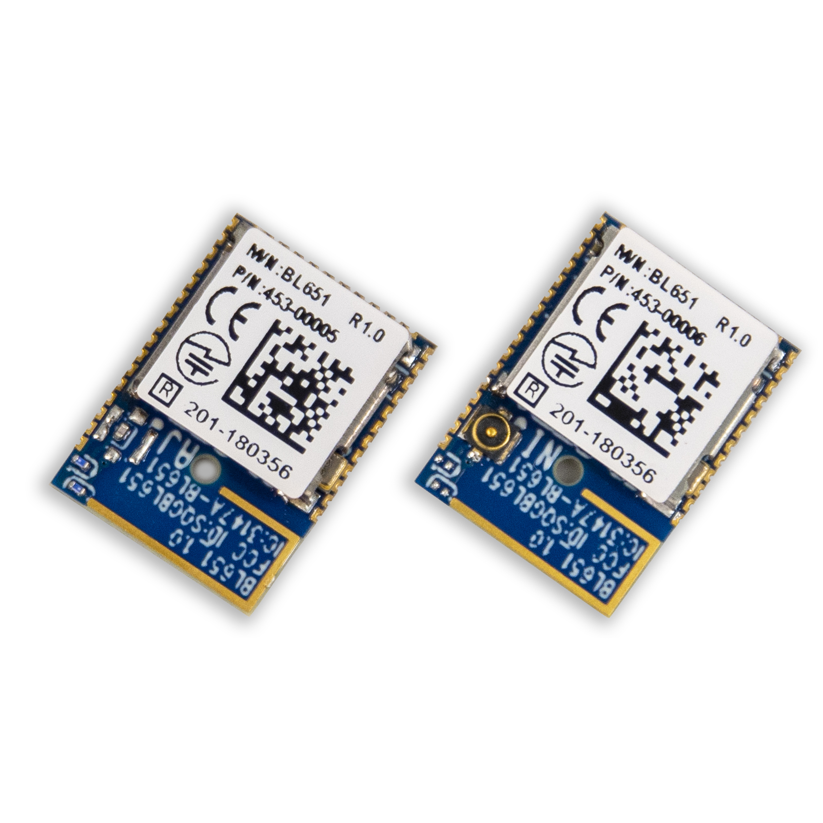
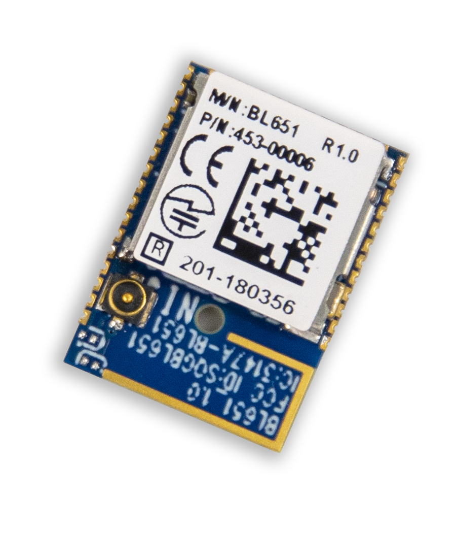
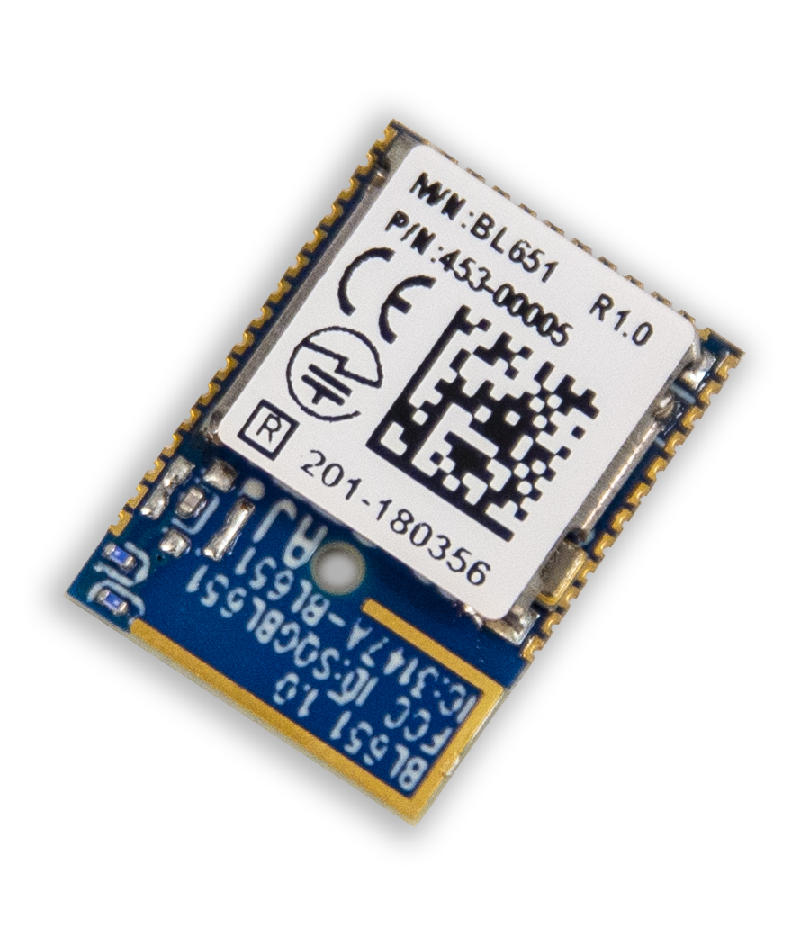
Ezurio's (formerly Laird Connectivity) BL651 Series contains the latest Nordic nRF52810 silicon with Bluetooth 5 Low Energy capabilities and groundbreaking ultra-low power performance. Building on Ezurio's multi generation module developments utilizing Nordic silicon (BL600, BL652, BL654) – now comes the latest series offering cost effective Bluetooth 5 enablement for simple Bluetooth LE applications.
The BL651 series exposes all the capabilities of the Nordic nRF52810 silicon in a small, fully certified module with simple soldering castellation for easy prototyping and mass production manufacturing. Use the Nordic SDK & SoftDevice or Zephyr Project to deliver your Bluetooth LE application.
Let Ezurio's innovative BL651 series and decades of expertise in Bluetooth module design speed your product to market.
In addition the BL651 series is 100% PCB footprint drop in compatible with the BL652 series of modules.
Specifications
| Part Number | Antenna Options | Antenna Type | Bulk or Single | Chipset (Wireless) | Frequency Range (Max) | Frequency Range (Min) | Frequency Range 2 (Max) | Frequency Range 2 (Min) | Logical Interfaces | OS/Software | Product Type | System Architecture | Technology | Type |
|---|---|---|---|---|---|---|---|---|---|---|---|---|---|---|
 Recommended for New Design (RND) Buy Now | IPEX MHF4 | External | Bulk - Cut Tape | Nordic nRF52810 | 2480 MHz | 2402 MHz | 13.56 MHz | 13.56 MHz | Serial, GPIO, I2C, SPI, ADC, PWM | Nordic SDK, Zephyr | Embedded Module | Hostless | Bluetooth 5.0, Single Mode (BLE) | Module |
 Recommended for New Design (RND) Buy Now | Internal | Bulk - Tape/Reel | Nordic nRF52810 | 2480 MHz | 2402 MHz | Serial, GPIO, I2C, SPI, ADC, PWM | Nordic SDK, Zephyr | Embedded Module | Hostless | Bluetooth 5.0, Single Mode (BLE) | Module | |||
Recommended for New Design (RND) Buy Now | Internal | Bulk - Cut Tape | Nordic nRF52810 | 2480 MHz | 2402 MHz | Serial, GPIO, I2C, SPI, ADC, PWM | Nordic SDK, Zephyr | Embedded Module | Hostless | Bluetooth 5.0, Single Mode (BLE) | Module | |||
Recommended for New Design (RND) Buy Now | IPEX MHF4 | External | Bulk - Tape/Reel | Nordic nRF52810 | 2480 MHz | 2402 MHz | 13.56 MHz | 13.56 MHz | Serial, GPIO, I2C, SPI, ADC, PWM | Nordic SDK, Zephyr | Embedded Module | Hostless | Bluetooth 5.0, Single Mode (BLE) | Module |
Development Kits
-
/filters:background_color(white)/2021-04/453-00062-K1_BoxContents-1200.png)
453-00062-K1
Additional DescriptionUSB-SWD Programming Kit: Includes mainboard, TC2050-IDC Tag Connect cable, 10-pin flat IDC cable, 1.2 m USB cable, and 2-pin jumper
Documentation
Certified Antennas
/filters:background_color(white)/s3fs-public/2018-10/ANT-DS-NanoBlue-Main-Image.png)
/filters:background_color(white)/2022-05/2.4ghz%20flexpifa.png)
/filters:background_color(white)/2018-11/mFlexPIFA-standalone-thumb_0.png)
Do you support any echoing support in the AT Interface app / implementation such as ATE1 & ATE0 for example?
Both ATE1 and ATE0 commands are pretty common in the modem world which would turn on and off the echo mode. In this case, any typed character(s) will be displayed to the screen or terminal – otherwise they are completely suppressed. This behaviour can be very useful for debugging or in some applications. However, there is currently no support for any echoing in our own AT Interface app and implementation. We recommend (if possible) to use a terminal application as an alternative such as UwTerminalX. In PuTTY, Tera Term or RealTerm this can be configured and enabled if needed.
Does the BL5340, BL5340PA, BL65x and Lyra BLE modules include the DC-DC LC filters on the module?
Yes, all BT modules
include the needed LC filter components required for DC-DC Converter operation.
Lyra P and Lyra S modules include a 2.2uH inductor on VREGSW output and 4.7uF capacitor to ground.
The nRF528xx used on the BL65x modules use two voltage regulators, REG0 and REG1. In Normal Voltage mode only REG1 is enabled. In High Voltage mode both REG1 and REG0 are enabled. The BL65x modules include 10uH and 15nH inductors on DCC output and 1.0uF capacitor to ground on REG1. REG0 includes a 10uH inductor on DCCH output and 4.7uF cap to ground.
Note: The BL651 module uses the nRF52810
which uses a single voltage regulator. The BL651 includes 10uH and 15nH
inductors on DCC output and 1.0uF capacitor to ground.
The nRF5340 used on the BL5340 and BL5340PA modules uses four voltage regulators, Main Voltage Regulator, Radio Voltage Regulator, High Voltage Regulator and a USB Regulator. In Normal Voltage mode the Main Voltage and Radio regulators are enabled while the High Voltage Regulator is disabled. In High Voltage mode the High Voltage regulator is enabled along with the Main Voltage and Radio regulators. The BL5340 module includes a 10uH inductor on the DCC outputs and 1uF capacitor to ground on the Main Voltage and Radio Voltage regulators. The High Voltage regulator includes a 10uH inductor on the DCCH output and 2.2uF capacitor to ground. The USB regulator uses an LDO only an no DC-DC filter components are needed.
How can I change the 32.768KHz Low Power Clock Source using nRF Connect SDK v2.x?
With nRF Connect SDK v2.0.0 and later only VS Code is made
available as an IDE as VS Code provides many features including both Command
Line Interface (CLI) and Graphical User Interface (GUI) in one environment.
Prior to nRF Connect SDK, the 32.768KHz source in nRF5 SDK applications defaulted to using the external crystal oscillator. The BL65x DVK’s populate an external 32.768KHz crystal but it is not connected via open solder bridges. Therefore, either the solder bridges need to be shorted to make the external crystal connection or change the clock source to internal RC Oscillator via the sdk_config.h file.
With nRF Connect SDK the correct 32KHz clock source is selected depending on the EVK. For BL654 DVK examples are built using internal RC oscillator. On BL5340 DVK the external crystal oscillator is selected as the DVK does close the solder bridge pads.
If the 32KHz clock source needs to be changed an application can change accordingly in the prj.conf file of the project. The following direct dependencies need to be added to prj.conf to override the default clock configuration.
External Crystal Oscillator and accuracy selection:
CONFIG_CLOCK_CONTROL_NRF_K32SRC_50PPM=y
Internal RC Oscillator and accuracy selection:
CONFIG_CLOCK_CONTROL_NRF_K32SRC_RC=y
CONFIG_CLOCK_CONTROL_NRF_K32SRC_500PPM=y
Kconfig dependencies can be found:
https://developer.nordicsemi.com/nRF_Connect_SDK/doc/2.3.0/kconfig/index.html
Using STTY with the USB-SWD
These instructions are intended for Linux or Macintosh OS. They may work using WSL, Cigwin, or other bash style terminals in Windows although this is untested.
It may be desired to communicate with a device attached to the USB-SWD without terminal emulation, I.E. Picocom, Screen, Putty. This can be useful for writing bash scripts, or if you're using Zephyr's "west flash" and would like a quick way to check your output.
- Verify you have the program "stty" available using the command "which stty", if this does not return a value you will need to install it. Fortunately "stty" generally comes standard with Linux and MacOS.
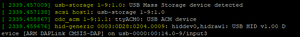
- Identify your serial device. This can be done using the command "dmesg -w" then connecting the USB-SWD. You will see output like this (In Linux).
- (Optional) Assign the device name to a variable, for example "DEVICE=/dev/ttyACM0".
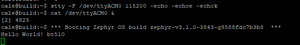
- Configure "stty" to talk with the device "stty -F $DEVICE 115200 -echo -echoe -echok"
- To see output from the device execute "cat $DEVICE &". This will send serial communication from the device to Linux's standard output. The "&" is to run this program in the background.
- Now press the reset button on the USB-SWD, you should see the output from your device. In this example the Zephyr "Hello World" example has been flashed to a BT510.
- (Optional) if you would like to send commands back to the device you can use "echo" or add an argument to your shell, "foo() { echo -n -e "$1\r" > $DEVICE; }". Now commands can be issued directly from the command line, for example "foo "my_command"" will send the string "my_command" to the device.
Do the NFC traces need to be controlled differential impedance between NFC1 and NFC2?
The NFC track does not need to be routed with a controlled differential impedance. The NFC antenna is different from the BLE antenna as it's differential and not 50 Ohm (each track is 50 Ohm single ended). Also, the frequency is very low, so the exact impedance doesn't matter as much. The inductance in the antenna is what matters for the NFC antenna. Since the antenna is differential, it's better to use a two-pin connection instead of U.FL which is a single ended connection.
The inductance of the antenna together with the NFC antenna tuning capacitors forms a resonant circuit that is tuned to the NFC frequency, 13.56 MHz. Any change in the connection wires to the antenna can be compensated with the tuning caps.
Does laird Connectivity support Nordic Enhanced Shock Burst (ESB)?
Yes, but software support should be sought direct from the Nordic Devzone as from Lairds point of view we provide only the hardware not the protocol.
Enhanced Shockburst (ESB) is a proprietary simple packet protocol for use in the Nordic modules. It is simple and easy to use and can give very low latency applications compared to BLE.
However, there is no encryption employed in ESB and ESB operates on a single frequency channel so there is no frequency immunity. You can implement your own encryption in upper layers though.
Also see Gazell (GZLL), which is another proprietary protocol from Nordic that builds on ESB.
Should I use nRFConnect SDK or nRF5 SDK with the Laird BL65x modules?
Nordic nRFConnect SDK, also known as NCS is based on the Zephyr RTOS with support for Laird modules based on nRF52 and nRF53
Nordic nRF5 SDK is a legacy bare metal SDK with support for Laird modules based on nRF51 and nRF52
You can choose either SDK but need to know that nRF5 SDK will not be supporting new features going forward. So if starting a new BL65x or BL5340 project then it is recomended to choose nRFConnect SDK.
See nRF Connect SDK and nRF5 SDK statement - Blogs - Nordic Blog - Nordic DevZone (nordicsemi.com) for more details
Why is SWDIO/SWCLK shorted to GND on my board?
According to the Nordic DevZone there are mainly two potential issues leading to a short on one of the SWD signals:
- ESD issue, likely when connecting an SWD programmer to the SWD signals.
- Connecting an SWD programmer while the target board is not connected to supply voltage.
Please make sure proper ESD precautions are taken into account (ESD wrist-strap, ESD base/mat) as well as make sure to first connect the supply voltage and then the SWD programmer.
Does the BL65x or BL5430 support Matter?
Matter can be supported on the BL5340 (nRF52840) and the BL654 when using the Nordic nRF Connect SDK. However, due to the memory requirements of Matter it can not be used on the BL653, BL652 nor the BL651 given their flash and RAM memory footprint.The BL653 (nRF52833) has 512K of Flash and 128K of RAM and BL652 and BL651 has less than that.
There are instructions on how to reduce the memory footprint for Matter in the documentation on the nRF Connect SDK Main branch, Memory footprint optimization » Matter, but even using this you will not be able to get it down to a size fitting on the nRF52833. With the steps from the optimization page with the light bulb sample the size was reduced to approximately 730 kB of flash and 170 kB of RAM when building for nRF52840, which is still way too high for the nRF52833. Additionally, there are possibilities that the Matter flash usage will grow more before the official release, as more bug fixes and things from the Matter specification will be added.
How can I read out the MAC address from a BLE module during test/production?
A fast and convenient way to read out the MAC address of each module during a test/production process would be through SWD from FICR (Factory information configuration registers) registers DEVICEADDR[0] and DEVICEADDR[1]. The following command will read the MAC address from our BLE modules:
nrfjprog --memrd 0x100000A4 --w 8 --n 6
Please note that reading the MAC address with nrfjprog will give the raw register content whilst using the SmartBASIC command ATI 4 (or by using sd_ble_gap_address_get() from nRF SDK) will automatically set the highest two bits to '11', since this is a requirement by the BT specification!
Please also note that reading from memory through SWD will halt the CPU. If you need your application firmware to start afterwards (like for performing some test sequence) you would have to run the CPU with
nrfjprog –run
More information on FICR registers are available in the respective data sheets, like this for nRF52840 / BL654.
Do I still have to list/qualify my product with the BT SIG even if I don't use the BT logo?
Yes, you need to qualify/list any product that uses BT SIG intellectual property, even if you do not use the logo or require interoperability with other BT devices. see here for more details. Qualify Your Product | Bluetooth® Technology Website
Does Laird have example code for a Windows Demo App which enables scanning and connecting to Bluetooth Low Energy peripheral IoT devices?
Unfortunately, we do not have an example of a Windows Bluetooth Low Energy application. If you require assistance with developing a Windows Bluetooth Low Energy application please contact one of our Sales Experts and let them know you are interested in a Design Services engagement and we will be happy to discuss your application requirements and provide a quote.
What factors influence the actual TX rate of the controller?
The actual TX rate is influenced by the PDU and MTU sizes along with the Connection Intervals and Slave Latency.
How many SPI Interfaces does the BL65x support
The BL654 Data sheet lists four SPI Interfaces (up to 8 Mbps) are supported. The data sheet is provided as a hardware guide and refers to the hardware itself. The Nordic nRF52840 MCU supports up to 4 SPI instances. However, the actual number of SPI interfaces depends on what SW is used for application development. If using smartBASIC for development there is one SPI instance that can be configured as SPI master.
The SPI port is opened via smartBASIC function SPIOPEN(). This function includes parameters that allow configuration of SPI Mode, SPI Clock Rate and SPI Flags. SPI pins cannot be configured and use the pins that are specified in the BL65x Data Sheet. Refer to smartBASIC Core Functionality Specification. SPI_CS is not controlled in smartBASIC firmware and must be controlled by the application through use of SIO pins.
For applications developed using Nordic SDK or Nordic Zephyr SDK the nRF528xx MCU supports up to 4 SPI Instances. There can be up to 4 SPI Master interfaces (SPIM Master) and up to 3 SPI Slave interfaces (SPIS) but not all at once. There are four total SPI interfaces and master/slave combinations are shared across those four instances. The nRF528xx also contains two I2C Instances which are shared with the two lower SPI instances via TWI. Refer to the latest nRF52xx data sheet for details.
How many I2C ports does the BL65x support
The BL65x Data sheet lists two I2C controllers (up to 400 Kbps) are supported. The data sheet is provided as a hardware guide and refers to the hardware itself. The Nordic nRF528xx BLE mcu’s support multiple I2C controllers. However, the actual number of I2C interfaces depends on what SW is used for application development. If using smartBASIC for development there is one I2C instance and that instance is a master, there is no slave support.
Referring to the smartBASIC Extensions guide for the various BL65x modules it states:
Note I2COpenEx() allows for SCL and SDA to be routed to other GPIO pins.
This function uses the same I2C instance but allows changing the pins it is operating on. The smartBASIC I2C driver does not support a second instance. The intent of this function is so multiple devices with the same I2C address can be used. Some devices support a single address, some have multiple addresses they can use. If a sensor with 2 possible addresses is used then a third cannot be added on the same bus because the address of 2 devices will clash, but it can be used on different pins. Another example is if one sensor only supports 100KHz mode but another that supports 250KHz. Different busses would need to be used so that the 250KHz signals do not cause undefined operation for the 100KHz sensor
For applications developed using Nordic SDK or Nordic Zephyr SDK then I2C interfaces supported by the particular nRF528xx BLE MCU can be used. Both master and/or slave operation is also supported. Refer to the nRF828xx data sheet for details.
What influence does the client have when it comes to notifications?
The Client must initiate the ability of the Server to send Notifications by writing to the CCCD descriptor for the Notified Characteristic on the Server.
Why are multiple EMPTY_PDU are being sent from the Master per connection interval?
The communications protocol for Bluetooth is a ping pong type style, so every connection event begins with the Master sending the slave a packet and the Slave then responds to that packet with any data it may have. Therefore, when the Master has no data to transmit it will send an EMPTY_PDU to the Server and the Server, if it has data to send, will send back the data in response. You can see this readily where there is no data transmissions, the Master and Slave ping pong EMPTY_PDU’s back and forth on every connection event, if Slave Latency was incorporated then during these periods of no data transmissions you would see Master send EMPTY_PDU and no response from Slave because it has no data to send and was allowed to skip the connection event because of it.
Can the BL5340 or BL65x use a different stack to support a hosted application?
Theoretically as long as whoever 3rd party BLE stack is used is tested and supported on Nordic nRF5340 or nRF528xx used on BL65x modules.
Laird would not have tested anything other than Zepher/nRF SDK.
A 3rd party CODEC could be used as well as long as it is targeted for nRF5340. However, licensing would need to be considered.
Is there a way to extend the shelf life of Laird modules?? If the shelf life cannot be extended in any way, what are the consequences of using modules after shelf life?
The shelf life statements are essentially to prevent mishandling of the product and not storing it properly. If the modules are still sealed in the package, stored at the proper temperature and have not been exposed to moisture they should be fine. However, when working with modules beyond their shelf life you MUST bake the modules before populating the them to your board. Failure to bake the modules could result in the yield rate dropping down lower than expectation due to popcorn or de-lamination on the modules. It is recommended that you follow IPC/JEDEC J-STD-033 which is the general standard for the handling, packing, shipping and use of moisture/reflow sensitive surface mount devices.
Our main concern is around the castellation/pads which solder the module to the board. It is imperative those pads do not get tarnished, as this would cause soldering issues. Humidity can affect solderability as well, as if there is any excess moisture in the solder on the module, during reflow of the module to the board, steam balls can essentially explode the solder and sometimes result in an open circuit (or possibly a short circuit).
As long as all of the moisture handling and temperature guidelines are being followed you will likely have no issues. It is further recommended that when you do the build with modules that have exceeded their shelf life that you start with a handful to perform a test run and do a final test to make sure all is working as expected. As long as there are no issues with the initial test run we would expect that you will not experience any problems.
What does the Bluetooth message "advertised data length corrected" indicate?
This is effectively a Bluetooth SPAM message. It indicates the advert data being parsed is less than a full advert record can be, in other words trailing zeroes were removed.
How do I select the 32.768kHz Low Power Clock Source in the new nRF Connect SDK
Customers using the new nRF Connect SDK from Nordic will need to change the low power 32kHz clock source when working with the BL65x family of products.
To do this in the new SDK using the Segger IDE follow the instructions here;
- In Segger Embedded Studio select Project --> Configure nRF Connect SDK Project
- Filter the list for 'osc' or drill down in the list to the Device Drivers --> Hardware clock controller support --> NRF Clock controller support --> 32KHz clock source
- Select the clock source based on your configuration/design:
- Without the optional external 32khz xtal, default configuration for our modules, select 'RC Oscillator'
- With the external 32Khz xtal connected to the module, select 'Crystal Oscillator'
With the correct value selected your code should build with the right clock source configuration and your application should run smoothly.
Can I use Windows to scan for my BLE Peripheral and Connect to it?
Laird does not provide a Windows utility for scanning and connecting to BLE devices. We are also not aware of any existing third party apps to do this either. Android and iOS are the best options for scanning for and connecting to BLE radios.
Where are BL651 Sample Applications Located?
The BL651 is for simple BLE applications, and does not support smartBASIC firmware due to its limited flash. Therefore, if you will be working with the BL651 you would need to program the module using a platform which supports working with Nordic's nRF52810 such as the Nordic SDK or Zephyr Project. Both Nordic and Zephyr Project offer sample code when you download and install their platform. Software development support requests will need to be directed to the resources for the platform selected.
How do I program BL65x modules in production or in the field (Tag-Connect)?
Consider using a PCB pad layout with support for Tag-Connect for JTAG which allows for easy, low cost programming in production or in the field.
Note: Laird recommends you use JTAG (2-wire interface) to handle future BL65x module firmware upgrades. You MUST wire out the JTAG (2-wire interface) on your host design , where four lines should be wired out, namely SWDIO, SWDCLK, GND and VCC. Firmware upgrades can still be performed over the BL65x UART interface, but this is slower (60 seconds using UART vs. 10 seconds when using JTAG) than using the BL65x JTAG (2-wire interface).
How can I connect a Bluetooth Low Energy Device to a PC?
Bluetooth Low Energy uses Services as opposed to the set of standardized profiles that exists for Classic Bluetooth. While some Bluetooth Low Energy services have been standardized by the Bluetooth SIG, the development of custom services is allowed to meet custom application requirements.
Because Bluetooth Low Energy uses a completely different protocol than Classic Bluetooth and supports custom services, Bluetooth Low Energy devices cannot connect to a computer through the typical Bluetooth configuration of a computer. Therefore, connecting to a PC requires writing and running a Bluetooth Low Energy Central Role/Client application to collect the data sent from the Bluetooth Low Energy peripheral modules. Application development for PCs and Mobile devices is outside the scope of our support. Alternatively, a BL654 USB dongle could be used as a BLE Central Role device, to collect the BLE data and pass it to the PC over a COM Port. However, you would still need an application to view and process the data received over that COM Port.
We generally recommend customers who are new to Bluetooth Low Energy obtain a copy of Getting Started with Bluetooth Low Energy to help them understand the Bluetooth Low Energy protocol and the GATT table. There are also many resources available online which explain this.
When Bluetooth Low Energy was first introduced and we launched our BL6xx product line (predecessors to the BL65x series) we produced the BL600 and BL620 smartBASIC Application Walkthrough document, which provides an overview of how Bluetooth Low Energy works and how a GATT table is constructed.
Do BL65x modules support Boundary Scan function?
Unfortunately, we do not offer Boundary Scan functionality on the BL65x modules.
We do understand it is harder to place and recommend during development the use of an X-ray or some other means to verify to soldering process.
Do I have to use the Segger branded debugger to program over the 2-wire SWD interface (JTAG) of the Nordic-based modules?
Yes, any programmer/debugger that supports the SWD 2-wire interface and the Cortex M4F processor should work with the Nordic-based modules. You can find information about the memory map in the nRF5xxxx Product Specification under the Memory and NVMC sections.
Is there a DVK for the BL651 module?
We do not offer a DVK for the BL651, however, as the BL651 and BL652 are pin for pin compatible, the DVK-BL652 can be used during development as the development platform. It is important you keep in mind that the BL651 has half the flash/RAM so it cannot support any central role functions such as scanning and initiating connections, and it is not capable of supporting smartBASIC firmware, therefore it will be necessary to flash the DVK with custom firmware, via the JTAG interface, based on the development platform that you elect to work with.
BL651 software development can be completed with any platform that supports working with the nRF52810 such as Nordic SDK, Zephyr Project or MyNewt to name a few.
Is it possible to use AT commands to configure BL651?
The BL651 cannot be configured using AT commands, as the AT command set available with the BL65x modules requires loading a smartBASIC Application. Because of the limited Flash and RAM available on the BL651 it cannot support the smartBASIC firmware and therefore, the AT Interface application cannot be loaded to the module. It must be programmed using any of the developer platforms that support working with the nRF52810, such as Nordic SDK, Zephyr Project, or MyNewt, among others. All of these platforms require flashing the BLE application via the JTAG Interface, therefore it is required that you bring out the JTAG interface in order to program the BL651 module for BLE operation.
Become an Ezurio Customer to Gain Exclusive Access to Our Design Experts
- Antenna Scans
- Antenna selection and placement
- Custom antenna design
- Worldwide EMC testing / certifications
- Embedded RF hardware / firmware design
- Cloud architecture and integration
- Mobile application development
- Product & Industrial Design
Buy Now
| Distributor | Part | In Stock | Region | Buy |
|---|---|---|---|---|
| Mouser | 453-00005 | 4004 | North America | Buy Now |
| DigiKey | 453-00005 | 0 | North America | Buy Now |
| DigiKey | 453-00005 | 0 | North America | Buy Now |
| DigiKey | 453-00005 | 0 | North America | Buy Now |
| Future Electronics | 453-00005 | 0 | North America | Buy Now |
| Mouser | 453-00005C | 499 | North America | Buy Now |
| DigiKey | 453-00005C | 0 | North America | Buy Now |
| Future Electronics | 453-00005C | 0 | North America | Buy Now |
| DigiKey | 453-00006 | 1082 | North America | Buy Now |
| DigiKey | 453-00006 | 1082 | North America | Buy Now |
| DigiKey | 453-00006 | 1000 | North America | Buy Now |
| Future Electronics | 453-00006 | 1000 | North America | Buy Now |
| Mouser | 453-00006 | 948 | North America | Buy Now |
| Mouser | 453-00006C | 2363 | North America | Buy Now |
| DigiKey | 453-00006C | 0 | North America | Buy Now |
| Future Electronics | 453-00006C | 0 | North America | Buy Now |
| Mouser | 453-00062-K1 | 13 | North America | Buy Now |
| DigiKey | 453-00062-K1 | 10 | North America | Buy Now |
Distributors
| Distributor | Phone Number | Region | Website |
|---|---|---|---|
| Arrow Electronics | 1-855-326-4757 +44 2039 365486 |
APAC, North America, South America, EMEA | Website |
| Avnet | 1-480-643-2000 +44 1628 512900 |
APAC, North America, South America, EMEA | Website |
| Braemac Australia, New Zealand, South East Asia | +61 2 9550 6600 +64 9 477 2148 |
APAC | Website |
| Cal-Chip Connect | 1-215-942-8900 |
North America | Website |
| DigiKey | 1-800-344-4539 |
North America, South America, APAC, EMEA | Website |
| EBV Elektronik | EMEA | Website | |
| Farlink Technology China, Hong Kong | +86 13266922199 |
APAC | Website |
| Farnell | 1-800-936-198 +44 3447 11 11 22 |
EMEA | Website |
| Future Electronics | 1-800-675-1619 1-514-428-8470 |
North America, South America, APAC, EMEA | Website |
| Glyn | +49-6126-590-0 |
EMEA | Website |
| Hy-Line Germany Only | +49 89 614 503 0 |
EMEA | Website |
| Jetronic China, Hong Kong and Taiwan | 852-27636806 |
APAC | Website |
| Laird Connectivity | 1-847-839-6925 +44 1628 858941 |
North America, South America, APAC, EMEA | Website |
| M2M Germany | +49-6081-587386-0 |
EMEA | Website |
| Martinsson | +46 8 7440300 |
EMEA | Website |
| McCoy South East Asia | +65 6515 2988 |
APAC | Website |
| Mouser | 1-800-346-6873 +44 1494 427500 |
North America, South America, APAC, EMEA | Website |
| RS Components | +852-2421-9898 +44 3457-201201 |
North America, South America, APAC, EMEA | Website |
| Ryoyo Japan | +81-3-3543-7711 |
APAC | Website |
| Solsta UK Only | +44 (0) 1527 830800 |
EMEA | Website |
| Supreme Components International India, South East Asia | +65 6848-1178 |
APAC | Website |
| Symmetry Electronics | 1-866-506-8829 |
North America | Website |
| Tekdis Australia and New Zealand | +61 3 8669 1210 |
APAC | Website |
| Telsys | +972 3 7657666 |
EMEA | Website |
| WPG | +44 1628 958460 |
EMEA | Website |