 Laird Connectivity is now Ezurio
LT1110 Series
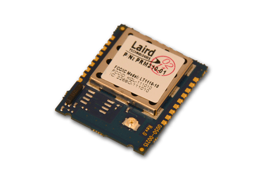
Overview
Laird's third generation 915 MHz FHSS module sets yet another standard for industrial RF communication. Based on proprietary FlexRF technology, this globally-accepted module will exceed most OEM application and performance requirements. Embedded with Laird's robust server-client protocol, the LT1110 permits an unlimited number of clients to synchronize to a single server for low latency communications. The server and all clients in a network can communicate with any radio in range via either addressed or broadcast packets. The configuration and test software allows OEMs to design and test networks to suit their applications. The enhanced API commands provide packet routing control and network intelligence. With its field-proven proprietary FHSS RF protocol and increased penetration at 915 MHz, the LT1110 rejects RF noise, excels in multipath scenarios, allows for co-located systems, and provides an extremely reliable communication link.
Note: Some variants of the LT1110 and related DVK and SDK variants have reached end of production and are available on a limited basis only. Find the End of Life Announcement in the Documentation tab below. Only the following part numbers are affected:
- PRM210
- PRM211
- PRM220
- PRM221
- PRM241
- DVK-PRM241
Specifications
| Part Number | Antenna Options | Antenna Type | Channels | Chipset (Wireless) | Compliance | Connector | Data Rate | Dimension (Height - mm) | Dimension (Length - mm) | Dimension (Width - mm) | Frequency Range (Max) | Frequency Range (Min) | Input Power | Logical Interfaces | OS/Software | Output Power | Power Consumption (Rx) | Power Consumption (Tx) | Product Type | Protocols | Range | Receive Sensitivity | System Architecture | Technology | Transmit Power (Max) | Weight | Wireless Specification |
|---|---|---|---|---|---|---|---|---|---|---|---|---|---|---|---|---|---|---|---|---|---|---|---|---|---|---|---|
| PRM240 Recommended for New Design (RND) Buy Now | U.FL Connector (x1) | External | 52 Channels | TI CC1110 | FCC | Pluggable | 230 kbps | 4 mm | 30 mm | 25 mm | 928 MHz | 902 MHz | 3.3V TTL | UART | Configuration and Test Software | 200mW | 30 mA | 230 mA | Embedded Module | FHSS Wireless Protocol | Outdoor: 3.2 miles. Indoor: 800 feet. | -89 dBm | Hosted | Proprietary RF (9xx MHz) | + 23 dBm | .353 oz (10 g) | 900 MHz Cable Replacement System |
Documentation
Does the RM024 or LT1110 support encryption, if so which encryption protocol is supported?
Neither the RM024 nor the LT11110 modules have support for encryption. For security these modules offer the following:
1. Proprietary protocol - the RM024 uses a proprietary protocol which will only communicate with other modules using the same proprietary protocol.
2. System ID - Unique system ID, similar to a password character or network number which makes eavesdropping more difficult. A receiving transceiver will not go in range of or communicate with another transceiver on a different System ID.
3. RF Channelization - The radio uses FHSS (Frequency Hopping Spread Spectrum) protocol in which the transceiver communicates using frequency bins spaced throughout the frequency band. The RF channel specifies the unique pseudo-random hopping sequence which will be used by the radios in the same system/network. This also makes eavesdropping more difficult.
4. (Optional) Vendor ID: The Vendor ID, like the System ID, can be used to uniquely identify a network. Radios with the Vendor ID set, only communicate with other radios with the same set Vendor ID. The Vendor ID is a protected EEPROM parameter, and its value cannot be read. It can only be written once. OEMs should be aware that improperly setting the Vendor ID can cause communication issues. Setting the Vendor ID to an unknown value effectively renders the radio unable to communicate in a network.
How many transmit retries should I use in my application and what is the cost associated with more retires?
Selecting the proper amount of retries for a system can make the difference between a successful wireless implementation and a failure. Wireless as a medium is not guaranteed and is subject to the effects of RF interference and multipath (multiple copies of the same signal arriving at the receiver out of phase with each other: resulting in a cancellation of the signal). Retries are used to overcome these effects. Each retry occurs on a different frequency. This is beneficial because interference present on the previous frequency is less likely to also be present on the new frequency. Also, multipath is affected by the wavelength of the signal and all of the reflections present in the environment: changing frequency changes the wavelength and severe multipath on one frequency could be less of a problem on the next frequency.
Retries are good for overcoming the effects of interference and multipath. Retries occur at the following rates:
| Product | Retry Period |
| AC4490/CL4490 | 20ms |
| AC4790/CL4790 | 50ms |
| LT1110 | 13.19ms |
| RM024 | 13.19ms |
When selecting the number of retries for your application, you should calculate a worst-case scenario where every retry fails and set your system timeouts accordingly. You will have to decide whether it is more important to potentially have longer timeouts (more retries) and good data integrity or shorter timeouts (less retries) and the potential for worse data integrity.
What can I do to minimize current consumption and optimize battery life in my LT1110/RM024 application?
The RM024 and LT1110 provide a couple of options for reducing power consumption for applications which will required the radio to operate on battery power:
- Cyclic Sleep Mode can be enabled on a client radio which causes the radio to sleep for a programmable period of time and wake for a programmable period of time. For additional information see the Application Note: Cyclic Sleep Mode available from the RM024 Product Page. While there is currently not an Application Note written specifically for the LT1110, the process is the same for both modules so the RM024 Cyclic Sleep App Note can be referenced for both modules.
- Deep Sleep Modes (PM2 & PM3): The OEM host can issue the Enter Deep Sleep Command, as outlined in the modules User Guide to minimize current draw: RM024 User Guide - Section 4.2.3 Enter Deep Sleep LT1110 User Guide - Utility Commands Section - Deep Sleep
While in Deep Sleep Mode the processor has all interfaces disabled, including RF and Serial. Two sleep modes are supported: PM2, and PM3:
- PM2: The radio can either be awakened by the Sleep Interrupt Pin (Force 9600), by a Hard Reset, or when the sleep timer, which is configured with the command, expires.
- PM3: The module can only be awakened by the Sleep Interrupt pin (Force 9600). The sleep timer is not active in PM3 and the bytes controlling the timer are disregarded and can be omitted from the command.
Additional considerations for maximizing battery life:
- Adding power control so you can programmatically disable VCC to the radio.
- Consider reducing the transmit power - test with lower transmit powers in sites typical of end user experience to see if this is an option.
- Where applicable, consider buffering data to create larger packets of RF data rather than sending several smaller packets.
- Holding the processor in Reset using the Reset pin will NOT enable a Low Power Mode
What is the default UART baud rate for RAMP modules?
The default baud rate for RAMP modules is as follows:
RM024: 115200 baud
LT1110: 115200 baud
AC4790: 57600 baud
AC4490: 57600 baud
Should I used Broadcast mode or Addressed Mode?
<body>
<p><strong>Broadcast Mode</strong> causes a radio to transmit to all radios on the same network in that coverage area. Broadcast mode can be configured on all devices in a network for a simple deployment.
It is typically configured on a server or device acting as the server/master in point-to-multipoint applications to enable the server to transmit its data to all devices on the network.
</p>
<p>In Broadcast Mode, the radio uses Broadcast Attempts to increase the odds of successful delivery.
Broadcast mode does not send an RF Acknowledgement from the receiver on successful receipt of the packet, because there are multiple radios listening to the transmission.
Therefore, the transmitter will send every packet out the number of times specified by the Broadcast Attempts setting.
</p>
<p><strong>Addressed Mode</strong> causes a radio to transmit to a specific radio on the network using the radio MAC Address to determine the receiving radio.
The MAC Address of the intended receiver is configured as the Destination Address.
In point-to-point applications typically the server and the client are direct addressed to each other while in point-to-multipoint applications the clients are typically direct addressed to the server.
When working with the masterless protocol of the AC4790/CL4790 the peers can be direct addressed to each other for point-to-point,
or for point-to-multipoint, the ones acting as clients/slaves would be direct addressed to the one acting as the server/master.
</p>
<p>In Addressed Mode, the radio uses Transmit Retries to increase the odds of successful delivery. With Addressed Mode the receiver will send a RF Acknowledgement upon successful receipt of the packet.
Therefore, the transmitter will only use as many retries as are required to successfully deliver the packet.
</p>
<p>Broadcast Mode is simple to deploy and is, therefore, very attractive to many designers.
However, Broadcast Mode introduces much more RF latency to a system than Addressed Mode due to the fact that there is no RF Acknowledgement.
Many systems will use both methods. For instance, in a network comprised of an access point and several clients/slaves to that access point,
the access point radio will be programmed in Broadcast Mode and the client/slave radios will be programmed into Addressed Mode.
</p>
</body>
With Laird RAMP radios, (CL4490/AC4490, CL4790/AC4790, LT1110, RM024) can I implement a design using just TX, RX and Gnd (three-wire interface) for UART?
Yes it is acceptable to implement a UART design which only uses TX (Transmit), RX (Receive) and Gnd (Ground) However, it is strongly recommended that your hardware monitor the CTS pin of the radio. CTS is taken High by the radio when its interface buffer is getting full. Your hardware should stop sending at this point to avoid a buffer overrun (and subsequent loss of data).
You can perform a successful design without monitoring CTS. However, you need to take into account the amount of latency the radio adds to the system, any additional latency caused by Transmit Retries or Broadcast Attempts, how often you send data, non-delivery network timeouts and interface data rate. Polled type networks, where the Server host requests data from the Client host and the Client host responds, are good candidates for avoiding the use of CTS. This is because no one transceiver can monopolize the RF link. Asynchronous type networks, where any radio can send to another radio at any point in time, are much more difficult to implement without the use of CTS.
I am able to test with the Development Kit hardware or ConnexLink Unit connected to my PC, but it does not work in my actual application, why not?
There are a number of issues that can prevent the RAMP development kit hardware or ConnexLink unit from functioning in your application. Here are a few:
- Null Modem Adapter/Cable: The Laird RAMP radios are DCE (Data Communications Equipment) devices. Typically, devices like PCs are considered DTE (Data Terminal Equipment) devices. Peripheral devices are classified as DCE. A DCE device can interface to a DTE device using a straight-through serial cable, such as the cable which ships with the development kits and ConnexLink units. When interfacing between two DCE (or two DTE) devices together, a null modem (or crossover) cable (or adapter) is required to swap pins and convert the signals accordingly. Therefore, if your end device hardware is a DCE (Data Communications Equipment) device, a null modem adapter or cable is required between your end device and the development kit or ConnexLink unit. The null modem adapter crisscrosses the TXD pin with the RXD pin, the CTS pin with the RTS pin and the DTR pin with the DCD/DSR pins. Null modem cables/adapters are available at most computer equipment retailers.
- System Packet Timeout: In applications that were originally designed without the intention of using wireless devices, typically the packet timeouts are very short (microseconds). Because of the system latency introduced by the wireless system, packets generally take several milliseconds to deliver (longer depending on the number of retries required). A system with a microsecond timeout will time out on every packet. Oftentimes, the timeout parameter in the software is adjustable and can be increased to account for the radio latency.
- Interface Baud Rate/Parity: The radio must be programmed to the same interface baud rate that your equipment is using. In addition to this, the radio must be programmed to the same data format that your equipment is using. The radio is programmed to use 8-N-1 data format (8 data bits, No parity, 1 stop bit). The radio supports a number of other formats including parity. See the User’s Manual for more details.
- Handshaking Pins: A number of applications use the extra handshaking pins available on the DB-9 connector (such as DTR, DSR, DCD and RI) to signal start, stop and special-case events. The radio can support these pin functions when Modem Mode is enabled in EEPROM. However, sometimes a special cable might be required to get the development kit pins to the right pins on your equipment.
Are your RAMP radios (AC4490/CL4490, AC4790/CL4790, RM024, LT1110) UL Certified for applications in C1D2 Environments?
While the some of our RAMP radios have been used in C1D2 environments, they are not certified for this. Extra certifications are required which are on the customer to get. However, we will supply the additional information necessary to obtain certification such as capacitance and inductance totals and BOMs as required. This information is only provided under NDA. To request the additional information required for such certifications please open a support ticket via our Support Portal.
Can the firmware be updated on the AC4490/CL4490 or AC4790/CL4790 in the field?
Unfortunately, no. The AC4490/CL4490 and AC4790/CL4790 can only be upgraded using a special tester (programming) device. However, radios should ship with the most current (stable) version, as there have not been any updates to the firmware for many years.
Other variations in firmware, indicated by the -01, -02, -03 included in the part number are regionally significant, and must be purchased with the correct firmware version for the region the radio will be deployed. The regional firmware versions cannot be interchanged on the radios. Please see FAQ: What is difference between AC4490/AC4790 product part numbers that end with -01, -02, -03? for additional information on the regional variants.
Note: if the part number does not include a -xx then it is loaded with the FCC/IC (-01) firmware.
I am not achieving the range documented in your manual, why not?
The range documented in our manual is the "theoretical" range, based on what is documented for the radio's chipset as achievable. The actual range is impacted by many factors, including but not limited to:
- Protocol used on the radio (For instance see FAQ: What is the difference between the AC4490 and AC4790?)
- Antenna selection
- Antenna Cable selection and length
- Board design
- Height of Antenna Installation
- RF Environment
To improve the range in your intended application we recommend the following:
- Direct address the radios for point-to-point applications. For point-to-multipoint applications, the server (or unit acting as a server in a masterless architecture) must be set to broadcast, but all clients should be set to auto-destination or direct addressed to the server
- Increase the transmit retries (applicable only when the radios are direct addressed or using auto-destination. As range increases, latency will increase, increasing the number of transmit retries will increase the chances of the packet being received. With each increase, test to determine the best setting for the intended application
- Where you are able, increase the height of the antenna placement, and ensure clear line of sight
- On the RM024 or LT1110 radios FEC (Forward Error Correction) can be configured to improve the range. This MUST be configured the same on ALL radios in the system. There are four configurations to choose from, taking into account the impact on throughput when configuring this feature. FEC is enabled by selecting one of the RF Profiles (ONLY available on RM024 and LT1110)
- Selecting a higher RF Baud Rate will provide increased RF bandwidth. However, selecting the lower RF Baud Rate will provide significantly improved range. Selecting fewer hops provides a shorter sync time, whereas more hops will provide better interference and collocated system immunity.
What is Sync-to-Channel and do I need it?
We run frequency hopping protocol on our transceivers with a fixed pseudo-random hopping sequence. This protocol yields superior interference rejection and multipath immunity. The Server radio sends timing beacons out on a regular interval. The Clients hear these beacons and synchronize their frequency hopping to the Server.
Though Servers cannot send packets to each other, they can hear the timing beacons sent out by other Servers. Normally, they simply ignore the beacons sent out by the other Servers. However, when Sync-to-Channel is enabled, they will listen for the beacons sent out by another Server and then synchronize their hop timing to that Server.
Why is this important? If two Servers (and their Clients) are operating in the same area and their frequency hopping is not synchronized to each other it’s possible that they might try to occupy the same frequency at the same time. In severe cases, they could interfere with each other on every frequency, causing very sluggish communications.
On the RAMP radios, what is the difference between "Broadcast Attempts" and "Max Transmission Retires"?
When the radios are Direct addressed to each other, meaning the MAC Address of the paired receiver radio is configured in the Destination Field, they are in what is known as Addressed Acknowledge Mode. When in this mode, the RF packet is sent out to the receiver designated by its Destination Address. Max Transmit Retries is used to increase the odds of successful delivery to the intended receiver. Transparent to the OEM (Other Equipment Manufacturer) Host - your device, the transmitter will send the RF packet to the intended receiver. If the receiver receives the packet free of errors, it will send the transmitter an acknowledgement. If the transmitter does not receive this acknowledge, it will assume the packet was never received and retry the packet. This will continue until the packet is successfully received or the transmitter exhausts all of its retries. The received packet will only be sent to the OEM Host if and when it is received free of errors.
When the radio is configured in Broadcast mode, by enabling Broadcast in the Radio Features section, the radio is in Broadcast Acknowledge Mode. While in this mode, the RF packet is broadcast out to all eligible receivers on the network. Broadcast Attempts is used to increase the odds of successful delivery to the intended receivers. Transparent to the OEM Host, the transmitter will send the RF packet to the receivers. If a receiver detects a packet error, it will throw out the packet. This will continue until the transmitter exhausts all of its attempts. Once the receiver successfully receives the packet it will send the packet to the OEM Host. It will throw out any duplicates caused by further Broadcast Attempts. The received packet will only be sent to the OEM Host if it is received free of errors.
How do I return my ConnexLink Radio, AC4490/AC4790, RM024, LT1110 radio to its default settings, can I use Show Defaults?
As per section 3.10 of the Laird Configuration and Utility User Guide, [Show Defaults] settings should ONLY be used as a reference and should NEVER be written to the radio.
!!!!WARNING!!!!
Writing the "show defaults" settings to a radio can result in the unit entering an unrecoverable state (bricked). If the radio enters this state a new radio must be purchased, it can not be repaired. After viewing the default settings using this feature, you should ALWAYS read the current settings using [Read Radio] prior to writing any changes to the radio with [Write Radio].
To restore the radio to its default state you will need to load an EEPROM file, containing the default settings, to the Laird Configuration and Test Utility software using [Load File] and then write these settings to the radio using [Write Radio]. It is recommended to save a copy of the default configurations to a file prior to altering the settings using [Save to File] feature in the Laird Configuration and Test Utility. If you do not have a file with the default settings saved please contact us via our Support Portal and we will provide you with a file containing the default settings for your specific radio.
Which Antennas can be used with the CL4490, CL4790, AC4490, AC4790, RM024, or LT1110?
Please reference the Approved Antennas list in the Datasheet (Hardware Integration Guide) for the specified ConnexLink Unit, or module.
- Datasheet (Hardware Integration Guide) - ConnexLink - CL4490
- Datasheet (Hardware Integration Guide) - ConnexLink - CL4790
- Datasheet (Hardware Integration Guide) - AC4490 Module
- Datasheet (Hardware Integration Guide) - AC4790 Module
- Datasheet (Hardware Integration Guide) - LT1110 Module
- Datasheet (Hardware Integration Guide) - RM024 Module
As noted in the Datasheet, you may use different antenna manufacturers than those listed as long as the antenna is of like type, and equal or lesser gain with similar characteristics to one of the ones listed.
How do I return my ConnexLink Radio, AC4490/AC4790, RM024, LT1110 radio to its default settings?
In order to return the radio to its default EEPROM settings it is necessary to load a previously saved file containing the default settings to the Configuration Utility and write the changes to the radio. If you did not save the default settings to a file, prior to changing the settings, please contact Laird Support through the Support Portal to request a file with the default settings for the purpose of restoring the radio to its default configuration.
The "Show Default" settings view in the Laird Configuration and Test Utility should NEVER be written to the radio, as these are for reference ONLY. Writing these to the radio can result in corrupting the radio to a point where it can become unrecoverable. After viewing the "Show Default" settings, the radio settings should always be READ again, prior to writing any changes to the radio, to prevent this from occurring.
Can I choose an RF Channel that is outside of Wi-Fi interference on the RAMP radios?
The RF Channel setting in our Laird RAMP modules and radios is not a true RF Channel or frequency of operation, it is actually just specifying a psuedo-random hopping sequence. The radios must, per the FCC, hop through every frequency in the band.
The RF Channel setting is only choosing a hopping pattern for navigating through all of the channels but each channel will be hopped to within a single pattern.
Can I get true full duplex operation from the RAMP products (RM024, AC4490, AC4790, LT1110, CL4490, CL4790)?
In the Laird RAMP line of products there is a feature called Full Duplex that leads one to believe they can talk upstream and downstream simultaneously. This is not the case, Full Duplex in the RAMP products gives a dedicated slot within the frame to the Server or Initiator and the second slot or next frame to the Client or Responder.
Do any of the RAMP products support XON-XOFF?
Xon-Xoff is not supported on any of our RAMP products. Flow control (handshaking) uses hardware RTS and CTS.
Become an Ezurio Customer to Gain Exclusive Access to Our Design Experts
- Antenna Scans
- Antenna selection and placement
- Custom antenna design
- Worldwide EMC testing / certifications
- Embedded RF hardware / firmware design
- Cloud architecture and integration
- Mobile application development
- Product & Industrial Design
Distributors
| Distributor | Phone Number | Region | Website |
|---|---|---|---|
| Arrow Electronics | 1-855-326-4757 +44 2039 365486 |
APAC, North America, South America, EMEA | Website |
| Avnet | 1-480-643-2000 +44 1628 512900 |
APAC, North America, South America, EMEA | Website |
| Braemac Australia, New Zealand, South East Asia | +61 2 9550 6600 +64 9 477 2148 |
APAC | Website |
| Cal-Chip Connect | 1-215-942-8900 |
North America | Website |
| DigiKey | 1-800-344-4539 |
North America, South America, APAC, EMEA | Website |
| EBV Elektronik | EMEA | Website | |
| Farlink Technology China, Hong Kong | +86 13266922199 |
APAC | Website |
| Farnell | 1-800-936-198 +44 3447 11 11 22 |
EMEA | Website |
| Future Electronics | 1-800-675-1619 1-514-428-8470 |
North America, South America, APAC, EMEA | Website |
| Glyn | +49-6126-590-0 |
EMEA | Website |
| Hy-Line Germany Only | +49 89 614 503 0 |
EMEA | Website |
| Jetronic China, Hong Kong and Taiwan | 852-27636806 |
APAC | Website |
| Laird Connectivity | 1-847-839-6925 +44 1628 858941 |
North America, South America, APAC, EMEA | Website |
| M2M Germany | +49-6081-587386-0 |
EMEA | Website |
| Martinsson | +46 8 7440300 |
EMEA | Website |
| McCoy South East Asia | +65 6515 2988 |
APAC | Website |
| Mouser | 1-800-346-6873 +44 1494 427500 |
North America, South America, APAC, EMEA | Website |
| RS Components | +852-2421-9898 +44 3457-201201 |
North America, South America, APAC, EMEA | Website |
| Ryoyo Japan | +81-3-3543-7711 |
APAC | Website |
| Solsta UK Only | +44 (0) 1527 830800 |
EMEA | Website |
| Supreme Components International India, South East Asia | +65 6848-1178 |
APAC | Website |
| Symmetry Electronics | 1-866-506-8829 |
North America | Website |
| Tekdis Australia and New Zealand | +61 3 8669 1210 |
APAC | Website |
| Telsys | +972 3 7657666 |
EMEA | Website |
| WPG | +44 1628 958460 |
EMEA | Website |